
Appendix B: Feature Kits
B-17
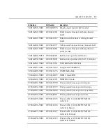
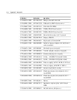
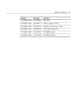
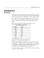
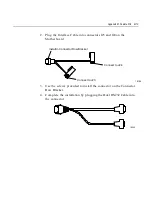
Dual RS-232 Port
7401-K070
The Pentium III/Celeron Motherboard has two RS-232 ports (9-pin D-
shell connectors, Com 1 and 2) directly on the board. The Dual RS-232
Port Kit is used to make two additional ports (Com 3 and 4) available.
Ports 1 and 3 on the board can be supplied with +12 V DC on Pin 9
when properly set up in the BIOS. The total power drawn by Ports 1
and/or 3 must be within the limits of the capabilities of the power
supply.
Refer to the following table for RS-232 pin-out information.
RS-232 DB-9 Male Connector Pin-Out
Pin
Port A
Port B
1
DCD
DCD
2
RXD
RXD
3
TXD
TXD
4
DTR
DTR
5
GND
GND
6
DSR
DSR
7
RTS
RTS
8
CTS
CTS
9
RI or +12*
RI
* If Port 1 or 3 is powered, pin 9 will be +12 V.
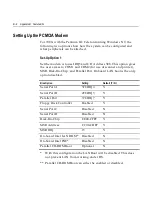
The BIOS allows flexibility in mapping resources. However, a fully-
loaded system (2 PCMCIA cards that require IRQs, four serial ports in
use, USB in use, parallel port in use, and MSR) may not have enough
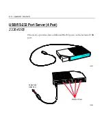
available IRQs to support all serial ports. Use a USB serial port
expander to overcome this PC architecture limitation.
Port 2 shares hardware resources with the IRDA connection; if IRDA is
in use, Port 3 is not available.
Содержание 7401 Web Kiosk
Страница 1: ...NCR 7401 Web Kiosk Release 2 3 Hardware User s Guide 16436 NCR B005 0000 1254 Issue D...
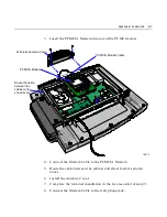
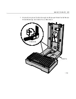
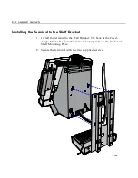
Страница 80: ...Chapter 2 Hardware Installation 2 21 2 Remove the Core Module from the Fixed Angle Mount 16397...
Страница 132: ...Chapter 3 Setup 3 23 5 Move the cursor to the Exit Menu select Save Changes Exit or Save Changes and press Enter...
Страница 154: ...Chapter 3 Setup 3 45 2 Press Enter and then select the desired setting from the drop down menu Other RS 232...
Страница 183: ...3 74 Chapter 3 Setup...
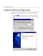
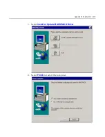
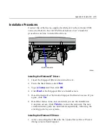
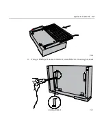
Страница 221: ...Appendix B Feature Kits B 13 3 Select Install or Update BACKPACK Driver 4 Select Finish to restart the computer...
Страница 232: ...B 24 Appendix B Feature Kits 5 Install the Antenna Cover and secure it with screws 2 16874 Wireless Antenna Cover...
Страница 249: ...Appendix B Feature Kits B 41 10 Slide the Keyboard Shelf onto the Bottom Plate and install the four screws 17372...
Страница 251: ...Appendix B Feature Kits B 43 12 Install a Strain Relief Bushing through the Mounting Bracket 18530 Strain Relief Bushing...
Страница 259: ...Appendix B Feature Kits B 51 5 Wrap the metal strap around the pole and loop it through the other end of the clamp 17356...
Страница 260: ...B 52 Appendix B Feature Kits 6 Snug the clamp and then crimp the metal strap with a pair of pliers 17357...
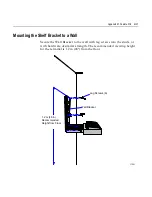
Страница 263: ...Appendix B Feature Kits B 55 11 Route the cables in the Wall Bracket as shown below 17359...
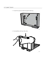
Страница 294: ...B 86 Appendix B Feature Kits 5 Push in the Core Module Support and lower the Core Module 6 Remove the Core Module 17345...
Страница 302: ...B 94 Appendix B Feature Kits 17729 Pole Mount Wall Mount...
Страница 311: ...Appendix B Feature Kits B 103 10 Route the cables in the Wall Bracket as shown below 17734 Mounting Screw on both sides...
Страница 326: ...B 118 Appendix B Feature Kits 2 Insert the end of the paper into the Paper Guide 16731...
Страница 328: ...B 120 Appendix B Feature Kits 4 Remove the cut paper waste from the Presenter 16965...
Страница 334: ...B 126 Appendix B Feature Kits 19050...
Страница 352: ...B 144 Appendix B Feature Kits 10 Install the CD ROM Bracket 3 screws 19232 Screws CD ROM Bracket...
Страница 366: ...Index 158 USB RS 232 port server 1 34 1 35 B 14 V Video subsystem 1 11 W Wireless LAN communications 1 12...
Страница 367: ...Index 159...
Страница 368: ...B005 0000 1254 September 2001 Printed on recycled paper...