© 2020 Carrier
33
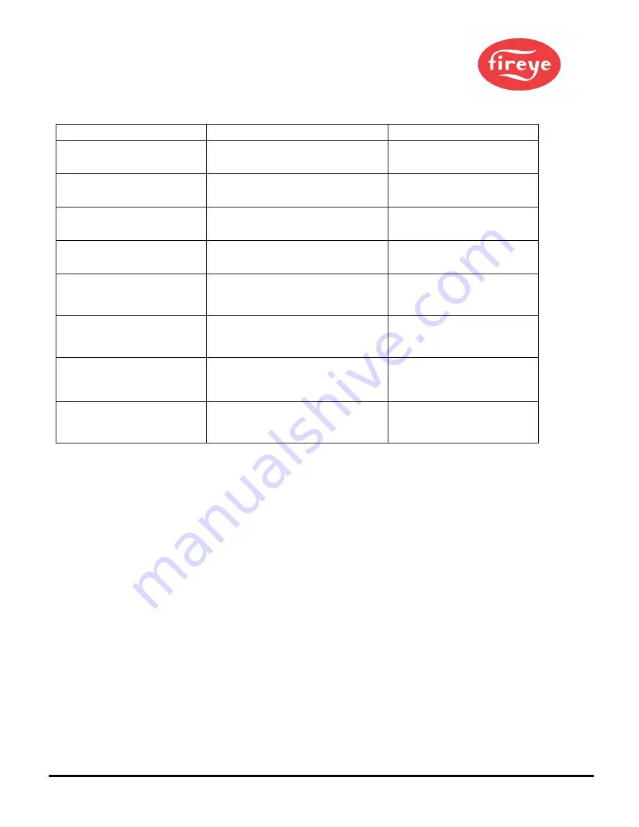
Group II Warning Messages (Can be suppressed, see Note 1)
Warning Message
Condition
Effect
FRx IR FEG LESS THAN MINIMUM
The IR FEG (Front-End-Gain) has dropped
below the MIN value selected by the user in
the IR Settings Menu (see Note 2).
The IR flame signal is driven to zero.
FRx IR FEG GREATER THAN
MAXIMUM
The IR FEG (Front-End-Gain) has risen above
the MAX value selected by the user in the IR
Settings Menu (see Note 2).
The IR flame signal is driven to zero.
FRx UV FEG LESS THAN MINIMUM
The UV FEG (Front-End-Gain) has dropped
below the MIN value selected by the user in
the UV Settings Menu (see Note 2).
The UV flame signal is driven to zero.
FRx UV FEG GREATER THAN
MAXIMUM
The UV FEG (Front-End-Gain) has risen
above the MAX value selected by the user in
the UV Settings Menu (see Note 2).
The UV flame signal is driven to zero.
FRx FAILED THE IR LIGHT CHECK
The IR source is likely not a real flame. The
scanner uses a “single-source” light check to
reject incandescent or fluorescent light
sources.
The IR flame signal is driven to zero.
FRx FAILED THE UV LIGHT CHECK
The UV source is likely not a real flame. The
scanner uses a “single-source” light check to
reject incandescent or fluorescent light
sources.
The UV flame signal is driven to zero.
TOO MUCH IR SIGNAL
The flickering (AC) component of the IR
source is too strong. The scanner cannot
properly detect the flame flicker.
(See note 3).
The IR flame signal will become
erratic or go to zero.
TOO MUCH UV SIGNAL
The flickering (AC) component of the UV
source is too strong. The scanner cannot
properly detect the flame flicker.
(See note 3).
The UV flame signal will become
erratic or go to zero.
Notes
1. Group II Warning messages are suppressed whenever “Do NOT Display” is selected under the FS Squelch Msgs
parameter in the CONFIG menu. This is the default setting. Although the
message
will be suppressed, if the Group II
Warning
condition
exists, the appropriate flame signal will still be driven to zero. To display the Warning messages,
select “Display” under the FS Squelch Msgs parameter.
2. An “FEG” Warning condition would occur if the user had manually changed the MIN or MAX value for the
FEG range in the IR or UV Settings Menus. The default settings for these parameters are 5 and 255 respectively.
3. Excess signal for a UV or IR sensor (depending on the scanner model) will be reduced by setting the Sensor’s (IR
or UV) Gain Range during AIM to a lower Setting. See Figure 25 on page 40. Additionally, installing a sight pipe orifice
will also lower the measurable UV or IR flame signals.
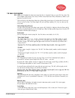
Select To Enter Configure Menu
Pressing the Select Key at this prompt will bring you to the Password Entry Screen before accessing the Configuration menu.
The Configuration Menu will allow the user to select F i l e S e l e c t M o d e , A u t o F l a m e R e l a y S e l e c t D e l a y ,
E n t e r / C h a n g e P a s s w o r d , R e s e t M a x T e m p , F S S q u e l c h M s g s , Active File, G a i n R a n g e ( IR o r UV
– depending on flame scanner).
From the Config Menu, the user can enter the following menus: Automatic Configuration, File Copy, 4 - 2 0 m A
S e t t i n g s , D a t e / T i m e , COMMs Settings, and Manual Configuration menus as well as Select to exit back to Main.
Содержание InSight 4 Series
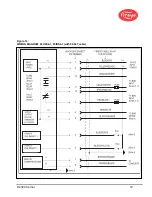
Страница 19: ... 2020 Carrier 19 Figure 14 WIRING DIAGRAM 95UVS4 1 95IRS4 1 with 59 547 cable ...
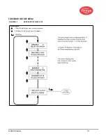
Страница 27: ... 2020 Carrier 27 THE MAIN STATUS MENU FIGURE 20 MAIN STATUS MENU LOOP ...
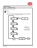
Страница 36: ... 2020 Carrier 36 THE CONFIG MENU FIGURE 23 CONFIG MENU LOOP ...
Страница 40: ... 2020 Carrier 40 THE AUTO CONFIG MENU FIGURE 25 AUTO CONFIG MENU LOOP ...
Страница 43: ... 2020 Carrier 43 THE FILE COPY MENU FIGURE 26 FILE COPY MENU LOOP ...
Страница 45: ... 2020 Carrier 45 THE 4 20 mA MENU FIGURE 27 4 20mA MENU LOOP ...
Страница 47: ... 2020 Carrier 47 THE DATE TIME MENU FIGURE 28 DATE TIME MENU LOOP ...
Страница 49: ... 2020 Carrier 49 THE COMMS MENU FIGURE 29 COMMS MENU ...
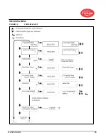
Страница 51: ... 2020 Carrier 51 THE MANUAL CONFIG MENUS FIGURE 30 ...
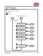
Страница 52: ... 2020 Carrier 52 MANUAL CONFIG MENUS continued FIGURE 31 ...

