28
®
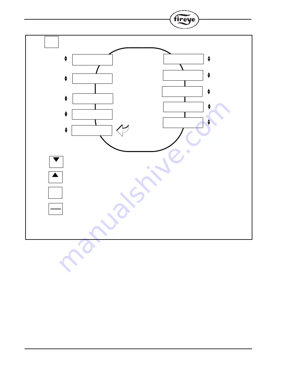
FIGURE 8.
CONTROL VARIABLE CONFIGURATION SUB-MENU
When selecting these values, the following rules may prove helpful:
1.
Select a value of MOD RNG to give desired result
2.
Add a derivative term to improve (reduce) the overshoot
3.
Add an integral term to eliminate the steady-state error
4.
Adjust MOD RNG, INTEGRAL, and DERIVATIVE until the desired overall response is
obtained.
Keep in mind that it is NOT necessary to implement all three variables (proportional, derivative, and
integral) into a single system. For example, if a PI controller gives a good enough response, then you
don't need to implement derivative controller to the system.
PCV PRES
30.0P
PCV INPUT
STEAM
START HERE
MODE
MDFY TO CHANGE
CUT OUT 2.0P
MDFY TO CHANGE
CUT IN
2.3P
DERIVATV TRM
0
INTEGRAL TRM
0
LIMIT ALM
25.0P
MRGNL ALM
24.0P
MOD RNG
1.5P
FROM
CTRL VAR
CONFIG >
PRESS
KEY FROM BOILER PARMS LOOP
MODE
PRESS
Key at anytime to exit sub-menu
Scrolls through menu, clockwise, decrement value
NEXT
Scrolls through menu, anti-clockwise, decrement value
BACK
PRESS
PRESS
MODIFY
RESET
To be modified/saved
PRESS
MDFY TO CHANGE
STM STPT
20.0P
MDFY TO CHANGE
MDFY TO CHANGE
MDFY TO CHANGE
MDFY TO CHANGE
MDFY TO CHANGE
MDFY TO CHANGE
MDFY TO CHANGE
Note: Example shown is 0-30 psig steam sensor. Use PCV INPUT to select steam.
Use PCV USE to select sensor type.
Содержание BurnerLogiX BLL510
Страница 79: ...79 NOTES...


