4.0 CONFIGURATION MENU
4-30
CyberCat 254/1016 Programming Manual
Rev 3, 08/2013
P/N: 06-539
4.4.1.1.1
PERIPHERAL DEVICE TESTING
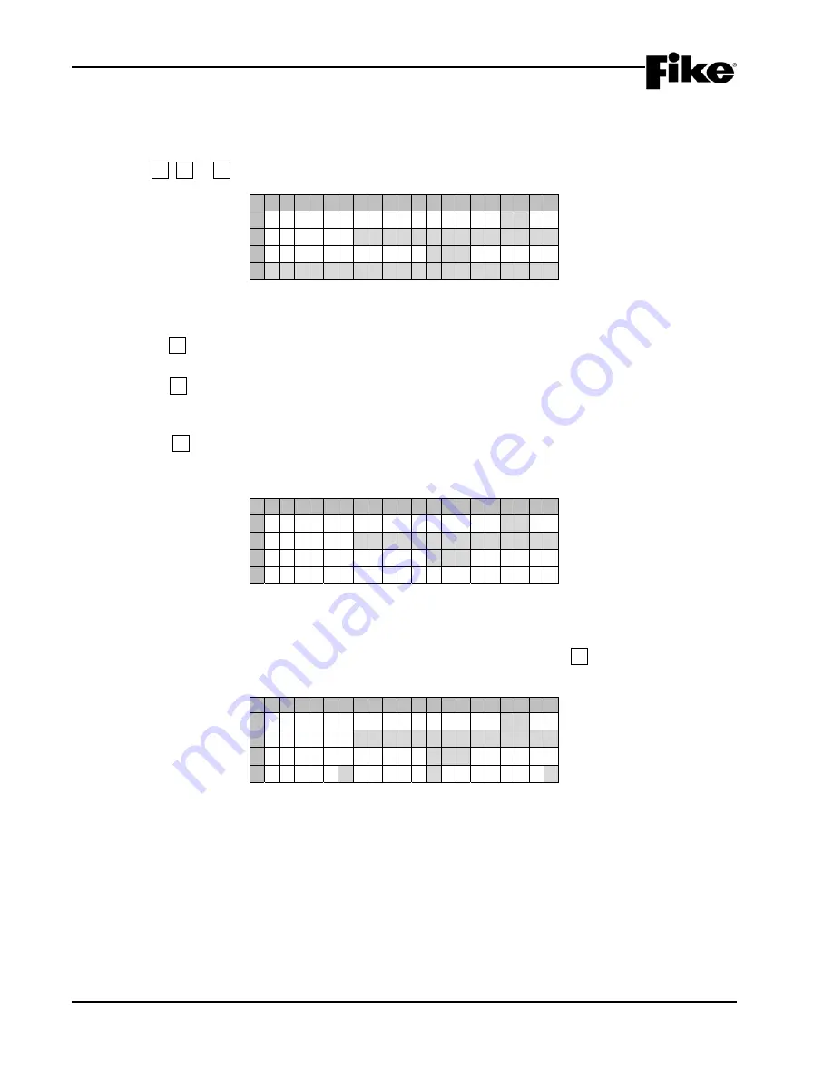
When the peripheral device type is set to either SMOKE CONTROL, SWITCH 20-ZONE, ANNUNC 20-ZONE
or 6 ZONE SMOKE EVAC, additional test features can be performed on the selected peripheral device by
pressing the F1, F2 or F3 keys:
1 2 3 4 5 6 7 8 9 0 1 2 3 4 5 6 7 8 9 0
A
P E R I P H E R A L
A D D R : 0 2
B
T Y P E :
S M O K E
C O N T R O L
C
S U P E R V I S E :
Y E S
Z : 0 0 0
D
* * S E N D I N G
L E D
T E S T * *
Exhibit 4-45: LED Test Screen
•
Row D – Toggles to display the feedback message for the test initiated.
Press F1 to send a LED test command to the selected peripheral device. The feedback message
“**SENDING LED TEST**” will be indicated on Row D of the display, as shown above.
Press F2 to force the selected peripheral device to perform a checksum test on its configuration
memory. The feedback message “**CHECKSUM TEST**” will be indicated on Row D of the display.
If the checksum fails, a trouble message “PER #aa CONFIG ERROR” will be reported to the panel.
Press F3 to force the selected peripheral device to perform a checksum calculation on its
configuration memory. The feedback message “**CHECKSUM CALC**” will be indicated on Row D
of the display, as shown below.
1 2 3 4 5 6 7 8 9 0 1 2 3 4 5 6 7 8 9 0
A
P E R I P H E R A L
A D D R : 0 2
B
T Y P E :
S M O K E
C O N T R O L
C
S U P E R V I S E :
Y E S
Z : 0 0 0
D
* * C H E C K S U M C A L C * *
Exhibit 4-46: Checksum Calc Screen
4.4.1.1.2
HOW TO PROGRAM A 256 LED GRAPHIC
When the peripheral device type is set to 256LED GRAPHIC, you can press the F1 key to toggle Row D of
the display between the peripheral custom message and additional configuration options, as shown below:
1 2 3 4 5 6 7 8 9 0 1 2 3 4 5 6 7 8 9 0
A
P E R I P H E R A L
A D D R : 0 2
B
T Y P E :
2 5 6 L E D
G R A P H I C
C
S U P E R V I S E :
Y E S
Z : 0 0 0
D
B U Z Z : Y
A C : N
B A T T : N
Exhibit 4-47: 256 LED Graphic Configuration Screen
•
Row D (BUZZ) - Allows you to Enable/Disable the piezo sounder on the graphic controller card
(
Y
/N).
•
Row D (AC) - Allows you to Enable/Disable supervision of the AC power input to the graphic
controller card (Y/
N
).
•
Row D (BATT) - Allows you to Enable/Disable supervision of the battery input to the graphic
controller card (Y/
N
).
Use the
◄►
arrow keys to position the cursor under each field; then use the
+/-
keys to toggle the
value at the cursor.


