


Page 8
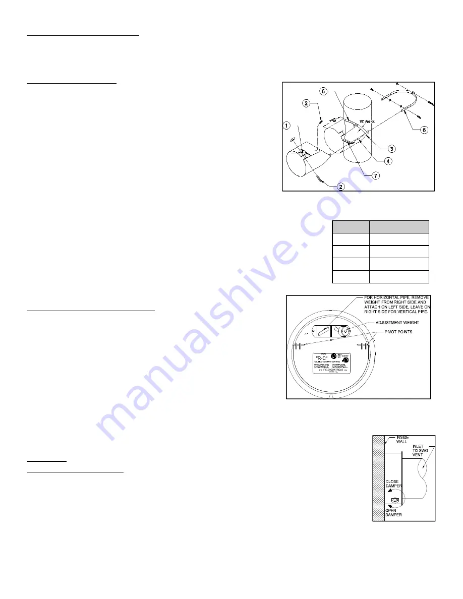
Figure 13
Figure 10
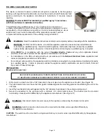
Figure 11
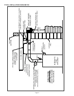
Figure 12
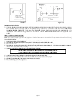
Table 4
RC SIZE B-DIMENSION
4 2
1/2
in.
5 2
1/2
in.
6 1
7/8
in.
7 2
5/8
in.
DRAFT CONTROL LOCATIONS
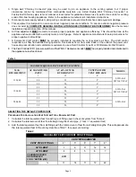
The draft control should be located as close as possible to a furnace or boiler and positioned as shown in Figure 10. It
should be typically 18” from appliance flue. Do not locate in a room separated from the appliance.
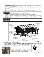
NOTE: When a sheet
metal tee is used instead of the collar, the “B” dimension must not be less than indicated for proper operation.
(See Figure
11 and Table 4)
COLLAR INSTALLATION
To attach the collar to the flue, see Figure 11 and follow the instructions
as follows:
1. Bend the two ears at the front corners of the collar outward.
Bend 90°, ¼” behind the single hole on the straps.
2. Insert clamping screw in ears on collar and bolt the remainder
of the collar together.
3. Hold the collar against the side of the flue in the exact position it
is to be installed (shown by dotted lines) and mark the outline of
the collar on the flue.
4. Cut a hole in the flue about ½” inside of the outline.
5. Make a series of cuts about ½” apart from the edge of this hole
to the outline marks.
6. Strap the collar to the flue pipe.
7. Bend the tabs formed by the series of cuts outward against the inside of the
collar to make tight joint.
8. Insert the draft control. (See Installation & Adjustment)
If flue pipe is made of material too heavy to bend out into collar, make the diameter of
the opening within ½” of the inside diameter of the collar. Seal with high temperature
RTV silicone or high temperature foil tape UL listed for the temperature of the
application.
For proper settings and operation of the burner and the draft, combustion testing
instrumentation and draft gauges must be used.
INSTALLATION AND ADJUSTMENT
NOTE: See sections on draft control locations and collar installation.
Insert the draft control into collar. The front face of the control must be
plumb. The pivot points must be level whether the control is on a
horizontal, vertical or sloping flue pipe. Use a spirit level, plumb and level
accurately. Secure the control in the collar by tightening the clamping
screws. If the collar is not supplied by Field, the control may be held in
place by small bolts or sheet metal screws so located as not to interfere
with the movement of the gate. When a sheet metal TEE is used instead
of the collar, the “B” dimension must not be less than indicated for proper
operation. The “B” dimension prevents the damper gate from obstructing
the flue passage way. (See Figure 11 & Table 4)
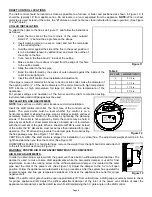
VERTICAL FLUES: The draft control is shipped for installation in a vertical flue. The adjustment weight should be in the
right hand slot when you face the control. (See Figure 12)
HORIZONTAL FLUES: For horizontal flues, remove the weight from the right hand slot and attach it
to the left hand slot as shown in Figure 12.
WARNING: PROPER AIR FLOW ADJUSTMENT MUST BE COMPLETED!
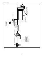
AIR FLOW ADJUSTMENTS
In order to obtain proper system draft, the power vent has a built in airflow adjustment damper. The
damper is used to make coarse draft adjustments while the barometric damper is used for finer
adjustments. Loosen the locking screw on the air flow adjustment damper. It is located on the outer
pipe near the inlet of the power vent. (See Figure 13) Adjust the damper to the 1/2 to full open
position. Follow the appliance manufacturer's start up procedures. After the system has operated for
several minutes and flue gas temperature stabilized. Check at the appliance flue outlet for proper
negative draft.
Note: (The draft control gate should be
open approximately 30
o
from vertical)
Use a draft gauge or velocity meter to check
for proper appliance draft. Adjust the airflow adjustment damper at the inlet of the power vent. Obtain at least the
appliance manufacturer’s specified draft level while still maintaining the 30
o
gate angle on the draft control.
Содержание SWG-AF Series
Страница 10: ...Page 10 WIRING DIAGRAM...
Страница 15: ...Page 15 TYPICAL INSTALLATION CONFIGURATION...
Страница 17: ...Page 17...
Страница 35: ...Page 17...


