


Page 7
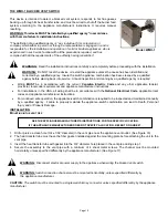
CAUTION
Do not support factory built chimney by inner wall of pipe.
C
ONNECTING
P
OWER
V
ENT
T
O
A
PPLIANCE
The vent system should be installed and supported. Never use Type B or Gas vents for venting solid or Bio-Fuel heating
appliances.
In the USA
In accordance with the latest version of NFPA 211 Standard for Chimneys, Fireplaces, Vents and Solid Fuel-
Burning Appliances. The International Mechanical Code and/or International Residential Code or in accordance
with any local codes of the authority having jurisdiction.
In Canada
In accordance with the latest version of
CSA B 365 Installation Code for Solid Fuel-Burning Appliances and Equipment.
A chimney pipe connector shall be supported for the design and weight of the material employed, to maintain clearances,
prevent physical damage and separation of joints. Check appliance installation instructions, the vent system may require a
particulate trap.
A chimney connector increaser or reducer may be required for connecting a power vent to the appliance vent
system. The reducer must be placed as close to the power vent as practical. The appliance flue diameter must
remain unchanged until reduced at the power vent.
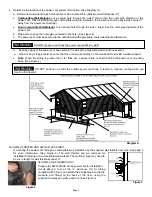
When installing a vent system near combustible materials, refer to the appliance installation instructions, NFPA 211
Standard for Chimneys, Fireplaces, Vents and Solid Fuel-Burning Appliances, The International Mechanical Code and/or
International Residential Code and local codes for guidance. Installation within Canada must be with accordance to the
latest version of CSA B 365 Installation Code for Solid Fuel-Burning Appliances and Equipment. If manufactured double
wall vent pipe is required or used for the installation, clearance should be based on the vent pipes rated clearance.
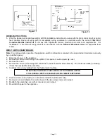
Route chimney pipe from appliance to power vent. Use a minimum number of elbows as practical. The horizontal section
of chimney pipe must slope upward from appliance to power vent.
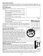
WIRING
NOTE:
Power Vent must be wired on a separate 15 amp GFI ground fault circuit breaker or equivalent 15 amp ground
fault over-current circuit separate from the appliance:
Wire the power vent motor:
In the USA
in accordance to the latest version of
NFPA 70 National Electric Code
In Canada
in accordance to the latest version of
C22.1 Canadian Electrical Code Part 1
Power Vent MUST BE GROUNDED. Check the ground circuit. Make certain the unit has been properly grounded. The
wiring should be protected by an over-current circuit device rated at 15 amperes.
Figure 7
Figure 8
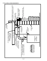
Figure 9
CAUTION
Do not pass single wall connector through walls, floors or ceiling.
CAUTION
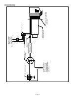
Ensure electrical wiring does not come in contact with any heat source. All line voltage and safety
control circuits, between the power vent and the appliance in the USA MUST be wired in accordance with the: NFPA
70 National Electrical Code for Class 1 wiring or equivalent (See Wiring Diagram on Page 10). In Canada in
accordance with: C22.1 Canadian Electrical Code Part 1.
Содержание SWG-AF Series
Страница 10: ...Page 10 WIRING DIAGRAM...
Страница 15: ...Page 15 TYPICAL INSTALLATION CONFIGURATION...
Страница 17: ...Page 17...
Страница 35: ...Page 17...


