


Page 13
Figure 18
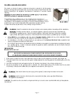
DO NOT DENT OR SCRATCH THE SURFACE OF THE THERMAL SWITCH.
IF THE THERMAL SWITCH IS DAMAGED, REPLACEMENT IS REQUIRED
.
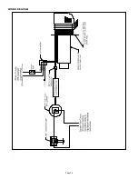
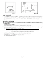
WIRING
INSTRUCTIONS
5. Wire the blocked vent switch according to MFG installation instructions in series with the limit control circuit or burner
feed controls. Route all wiring with an acceptable wiring enclosure in accordance with the current
CSA C22.1
Canadian Electric Code Part 1
and any other applicable federal, provincial and local code requirements. For
installations in the USA all wiring shall be in accordance with the
National Electrical Code
and applicable local
codes.
WMO-1 SWITCH MAINTENANCE:
Note:
For continued safe operation, the appliance-switch combination is required to be inspected and maintained annually
by a qualified agency
.
1. Disconnect power to the appliance.
2. Remove the two screws holding on the WMO-1 blocked vent switch assembly cover.
3. Remove
the
cover.
4. Remove the two screws holding the control box to the heat transfer tube assembly. The control box slides, unlocking
it from the heat transfer tube assembly.
5. Carefully remove any buildup from the thermal switch surface.
6. Clear and remove any buildup or obstruction inside the heat transfer tube.
7. Remount, lock and refasten the control box with the two screws removed in step 4.
8. Reattach the assembly cover with screws removed in step 2.
9. Re-establish power to the appliance.
Figure 17
Содержание SWG-AF Series
Страница 10: ...Page 10 WIRING DIAGRAM...
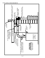
Страница 15: ...Page 15 TYPICAL INSTALLATION CONFIGURATION...
Страница 17: ...Page 17...
Страница 35: ...Page 17...


