


Page 11
Figure 15
Figure 16
MAINTENANCE
1.
Motor:
Inspect the motor once a year - motor should rotate freely. To prolong the life of the motor, it must be
lubricated with six drops of SWG Superlube, Part # 46226200, annually.
2.
Wheel:
Inspect the power vent wheel annually to clear any soot, ash or coating which inhibits either rotation or air
flow. Remove all foreign materials before operating.
3.
Vent System:
Inspect all vent connections annually for looseness, for evidence of corrosion, build up of soot and
for flue gas leakage. Replace, seal or tighten pipe connections if necessary. Check the power vent choke plate to
insure it is secured in place. Check the barometric draft control, if installed, to insure the gate swings freely.
4.
System Safety Devices:
With the heating system operating, disconnect the pressure sensing tube from the
pressure switch. This will stop the burner feed operation. Re-connecting the tube will restart the burner feed
system.
REPLACEMENT PARTS
Should the motor blower wheel assembly need replacement, the following items are available. The SWG-AF Repair Motor
Kit contains the Motor and Blower Wheel. It is factory assembled to a mounting bracket.
MODEL
REPAIR MOTOR KIT
SWG-4AF 46544400
SWG-5AF 46544500
SWG-6AF 46544600
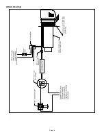
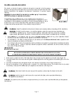
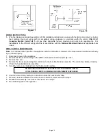
REMOVAL AND INSTALLATION OF THE SWG-AF SERIES POWER VENT MOTOR ASSEMBLY
R
EMOVAL
1. Remove the motor enclosure cover by loosening the four screws.
2. Open the electrical box on the motor and disconnect the conduit and wires from the
motor. (See Figure 15)
3. Remove the four nuts securing the motor assembly, and pull the motor assembly
straight off of the unit. (See Figure 16)
4. Clean off any build-up inside the blower wheel housing and blower wheel.
I
NSTALLATION
1. Align holes in the circular cover plate with holes in the motor mount bracket on
the motor assembly. (See Figure 15)
2. Slide motor assembly onto protruding threaded studs on the power vent body.
The exhaust chute must be pointing downward. Replace the four nuts securely to
the threaded studs. (See Figure 16)
3. Re-attach flexible conduit and wires to motor and secure cover on the electrical
box.
4. Install motor cover with the side louvers pointing downward.
CAUTION
Avoid applying excess pressure on the blower wheel when
cleaning off any build-up of material. This will cause an imbalance of the blower
wheel which results in excessive vibration and premature motor failure.
Содержание SWG-AF Series
Страница 10: ...Page 10 WIRING DIAGRAM...
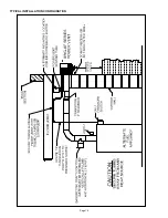
Страница 15: ...Page 15 TYPICAL INSTALLATION CONFIGURATION...
Страница 17: ...Page 17...
Страница 35: ...Page 17...


