Field Controls SWG-AF Series Скачать руководство пользователя страница 18


Page 18

Limited Warranty 


Field Controls, LLC (“Company”)


warrants that the products listed below, shall be free from defects in material and 

workmanship under normal use for the limited period indicated, from the date of manufacture, subject to the provisions 
below. 

Five (5) years 


Field Controls Direct Vent Systems (FDVS), Field Oil Vent Kits (FOVP) – sold to OEM accounts only 


Eighteen (18) months 


UV-Aire Air Purifiers, Power Vents, Vent Hoods, SWG and Combovent Power Vents, Control Kits (CK’s), Motor Assemblies, 
Combustion Air Systems, Draft Controls, Draft Inducers, Air Boosters, Safety Switches, Vent Caps, Condensate Pumps, Gas Vent 
Dampers, ClearWave, Humidifiers and Replacement Parts 


***************** 

Company warrants that the products listed below, shall be free from defects in material and workmanship under normal 
use for the limited period indicated, from the date of purchase by the consumer, subject to the provisions listed below. 


Ninety (90) days 


UV lamps/bulbs  

***************** 

Provisions: 

1. 

During the limited warranty period, Company, or its authorized service representative, will repair or replace, at Company’s 

option, without charge, a defective Product.  Product that is repaired may be repaired with new or refurbished replacement parts. 
Product that is replaced may be replaced with a new or refurbished product of the same or similar design. Company will return repaired 
or replacement Product to customer in working condition. Labor charges are not covered as part of the limited warranty. 

2. 

With regard to UV lamps/bulbs, customer shall be required to include a "valid proof of purchase" (sales receipt) identifying the 

Product purchased (Product model or accurate date code information) and the date the Product(s) was purchased.  

3. 

Product whose warranty/quality stickers, Product serial numbers plates or electronic serial numbers have been removed, 

altered or rendered illegible shall not be covered under the limited warranty.  

4. 

Defective Product must be returned to Company, postage prepaid. 

5. 

I

N NO EVENT SHALL 

C

OMPANY BE LIABLE FOR ANY INDIRECT

,

 SPECIAL

,

 INCIDENTAL

,

 CONSEQUENTIAL

,

 OR SIMILAR DAMAGES 

(

INCLUDING

,


BUT NOT LIMITED TO LOST PROFITS OR REVENUE

,

 INABILITY TO USE 

P

RODUCT

,

 OR OTHER ASSOCIATED EQUIPMENT

,

 THE COST OF SUBSTITUTE 

EQUIPMENT

,

 AND CLAIMS BY THIRD PARTIES

)

 RESULTING FROM THE USE OF 

P

RODUCT

.

 Some states do not allow the exclusion or limitation of 

incidental or consequential damages, so the above limitation or exclusion may not apply to you.  

6. 

T

HIS WARRANTY AND REMEDIES ARE EXCLUSIVE AND IN LIEU OF ALL OTHER WARRANTIES

,

 REMEDIES AND CONDITIONS

,

 WHETHER ORAL

,


WRITTEN

,

 EXPRESS

,

 STATUTORY OR IMPLIED

.


T

O THE EXTENT PERMITTED BY LAW

,


C

OMPANY DISCLAIMS ALL IMPLIED AND STATUTORY WARRANTIES

,


INCLUDING

,

 WARRANTIES OF MERCHANTABILITY AND FITNESS FOR A PARTICULAR PURPOSE

.


7. 

Company makes no warranty of any kind in regard to other manufacturer’s products distributed by Company. Company will 

pass on all warranties made by the manufacturer and where possible, will expedite the claim on behalf of the customer, but ultimately, 
responsibility for disposition of the warranty claim lies with the manufacturer. 

8. 

Product that has been subjected to misuse, accident, shipping or other physical damage, improper installation or application, 

abnormal operation or handling, neglect, fire, water or other liquid intrusion are not covered by the warranty. 


P/N 46576900 3/10

Содержание SWG-AF Series

Страница 1: ...quirements of the authority having jurisdiction WARNING Read the installation instructions carefully and completely before proceeding with the installation For continued safe operation the appliance v...

Страница 2: ...presentative is engaged in and is responsible for installation and operation of solid or bio fuel heating appliances Who is experienced in such work familiar with all the precautions required and has...

Страница 3: ...to air flow fluctuations during operation Fluctuations occur from wind loads on the outlet of the power vent house de pressurization and ventilation requirements use a Field Controls Type M or RC Bar...

Страница 4: ...to installation location Diagram A Page 5 for typical locations a The exit termination of mechanical draft systems shall not be less than 7 above grade when located adjacent to public walkways b A ven...

Страница 5: ...unit mounts directly on the wall board to provide a stable support Note When the siding is greater than 1 2 thick use a spacer plate or board behind the power vent mounting base See Figure 2 5a SWG A...

Страница 6: ...iece Backing Plate Installation a Position Upper Backing Plate Half on the inside wall Place plate half on inside wall and up to the vent body At the same time Put the air pressure sensing tube throug...

Страница 7: ...ical Code and or International Residential Code and local codes for guidance Installation within Canada must be with accordance to the latest version of CSA B 365 Installation Code for Solid Fuel Burn...

Страница 8: ...draft control into collar The front face of the control must be plumb The pivot points must be level whether the control is on a horizontal vertical or sloping flue pipe Use a spirit level plumb and l...

Страница 9: ...s located Turn on clothes dryers any exhaust fans such as range hoods and bathroom exhausts so they operate at maximum speed Do not operate a summer exhaust fan If after completing Steps 3 through 7 i...

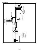
Страница 10: ...Page 10 WIRING DIAGRAM...

Страница 11: ...ntains the Motor and Blower Wheel It is factory assembled to a mounting bracket MODEL REPAIR MOTOR KIT SWG 4AF 46544400 SWG 5AF 46544500 SWG 6AF 46544600 REMOVAL AND INSTALLATION OF THE SWG AF SERIES...

Страница 12: ...y maintain the appliance switch combination can lead to Death Personal Injury and or Property Damage INSTALLATION MOUNTING IN THE VENT PIPE 1 Drill or pierce a clean hole 3 4 1 32 diameter in the vent...

Страница 13: ...local codes WMO 1 SWITCH MAINTENANCE Note For continued safe operation the appliance switch combination is required to be inspected and maintained annually by a qualified agency 1 Disconnect power to...

Страница 14: ...after the appliance has operated a sufficient time to establish stable combustion adjust pressure switch sensitivity by turning pressure switch adjustment screw clockwise See Figure 19 until burner f...

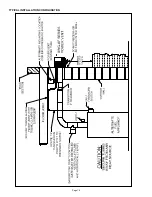
Страница 15: ...Page 15 TYPICAL INSTALLATION CONFIGURATION...

Страница 16: ...ystem as a guide for tune up or service information annually DATE EQUIPMENT SETUP INFORMATION Heating Appliance BTU HR Input Vent System Draft Before Barometric Draft Control Vent System Draft After B...

Страница 17: ...Page 17...

Страница 18: ...t identifying the Product purchased Product model or accurate date code information and the date the Product s was purchased 3 Product whose warranty quality stickers Product serial numbers plates or...

Страница 19: ...ctions de pose avec attention et en entier avant de proc der la pose Pour assurer un fonctionnement sans danger l ensemble appareil de chauffage et syst me d vacuation doit tre contr l et entretenu ch...

Страница 20: ...e type de travaux est familiaris e avec les pr cautions de rigueur et est en r gle vis vis des autorit s comp tentes L installateur doit crire ou imprimer son nom son num ro de t l phone et la date d...

Страница 21: ...e blocage d vacuation WMO 1 doivent IMP RATIVEMENT tre correctement install s et assurer un verrouillage appropri du circuit d alimentation du br leur de l appareil Table 1 TABLEAU DE DIMENSIONS DE L...

Страница 22: ...ssus du niveau du sol lorsqu elle est contigu des voies pi tonnes publiques b Un syst me d vacuation doit se terminer au moins 0 9 m 3 pi au dessus de toute prise d air forc e plac e moins de 3 m 10 p...

Страница 23: ...nlev pour les poses travers des murs en mat riaux non combustibles Il peut tre n cessaire de couper le manchon d embo tement mural la longueur pour les paisseurs de mur de moins de 20 cm 8 po 5b S RIE...

Страница 24: ...ement derri re le plateau de fixation de l vacuation forc e voir Figure 5 Pose de la plaque de fixation en deux pi ces a Placer la demi plaque de fixation sup rieure sur l int rieur du mur Poser la de...

Страница 25: ...Code d installation des appareils combustibles solides et du mat riel connexe Si un conduit d vacuation pr fabriqu double paroi est requis ou utilis pour l installation le d gagement doit tre bas sur...

Страница 26: ...b Les points de pivotement doivent tre de niveau que le r gulateur soit pos sur un tuyau de fum e horizontal vertical ou inclin l aide d un niveau bulle v rifier l aplomb et le niveau avec pr cision A...

Страница 27: ...ouve l appareil Faire fonctionner tous les s che linge ventilateurs d extraction tels que hottes de cuisine et ventilateurs aspirants de salle de bain leur vitesse maximale Ne pas faire fonctionner de...

Страница 28: ...ffage Se reporter aux instructions de pose de l appareil Contacteur de blocage d vacuation WMO 1 Contacteur de contr le de tirage DIP 1 Connecteur de tube de dia ext po jusqu 15 m 50 pi de l vacuation...

Страница 29: ...CHANGE Si l ensemble moteur turbine doit tre chang les articles suivants sont disponibles Le n cessaire de r paration de moteur SWG AF comprend le moteur et la turbine Il est mont sur un support de fi...

Страница 30: ...mauvais entretien de l ensemble appareil commutateur pr sente un danger de mort de blessures corporelles et de d g ts mat riels POSE POSE DANS LE CONDUIT D EVACUATION 1 Percer ou forer orifice propre...

Страница 31: ...s tout le c blage doit tre en conformit avec le National Electrical Code et les codes locaux en vigueur ENTRETIEN DU COMMUTATEUR WMO 1 Remarque Pour assurer un fonctionnement sans danger l ensemble ap...

Страница 32: ...jusqu ce que l alimentation du br leur s arr te Tourner ensuite la vis de r glage dans le sens inverse jusqu ce que l alimentation du br leur se remette en marche Tourner la vis de r glage de de tour...

Страница 33: ...ES DE PLANCHER AVEC DES COLLIERS POUR TUBE OU QUIVALENT MUR LE CLAPET DE R GULATION DE TIRAGE BAROM TRIQUE DOIT TRE POS D APLOMB VERTICALEMENT ET DE NIVEAU HORIZONTALEMENT ATTENTION FIXER LE TUBE L CA...

Страница 34: ...pour les r glages ou la maintenance annuels DATE DONN ES INITIALES DU MAT RIEL Puissance de l appareil de chauffage en BTU h Tirage du syst me d vacuation avant le r gulateur barom trique Tirage du sy...

Страница 35: ...Page 17...

Страница 36: ...ocollants de garantie qualit les plaques de num ro de s rie du Produit ou les num ros de s rie lectroniques ont t enlev s alt r s ou rendus illisibles n est pas couvert aux termes de la garantie limit...

Отзывы: