


15
4. InstallatIon
4.1 Power requirements
The PowerWizard series of generating set controls require a nominal voltage of 12 Vdc or 24 Vdc. If batteries are used for
operating power, a charging source such as an alternator or battery charger is necessary to maintain a stable supply voltage.
Under steady state operation, the PowerWizard controllers on 12V sets have less than 1A current draw (not including any relay
loads). This value will be lower for controllers on 24V sets.
This current drain can be reduced by approximately a factor of 7 by using the Reduced Power Mode option (RPM). However it is
recommended that a generating set at rest or in storage for prolonged periods should have either the battery charger or isolator
switch option fitted.
When connecting the PowerWizard generating set control to the DC power source, make sure that there is only one common
connection to the negative potential of the power source. Make extra effort to avoid any ground loops in the DC electrical
system. A single point common ground for electronics is recommended at the negative battery terminal or Power Distribution
Box. Each electronics subsystem and major engine subsystem should have its own DC network so that they do not interfere with
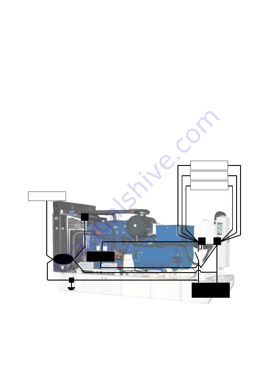
each other. An example is shown in Figure 5.
As shown in the figure all electronics are electrically isolated from higher current loads, such as the starter motor. All electronics
have a common Power Bus and Single Point Reference. The chassis ground is a common Power and Transient Ground.
The electronics, such as sensors and control modules, have isolated power source paths. High current loads such as starters and
solenoids can cause interference and possibly damage to low current loads, such as controllers and sensors. Extra effort must be
made to keep the high current and low current loads electrically separated. The two types of loads may share common
(+) and (-) battery connections, but they should not be electrically connected. This strategy ensures maximum isolation between
high current and low current loads.
Electronic Subsystem 1
Electronic Subsystem 2
Electronic Subsystem 3
Generator Set
Subsystem Loads
Engine ECM
- +
Battery
Starter
Generating Set Isolation DC
Supply System
figure 5: Generating Set network Isolation
The battery disconnect switch is located on the negative leg of the battery supply. If a battery charger is to be used, it should be
connected on the battery side of the disconnect switch, so as not to power the electronics. Most battery chargers are not to be
used as power supplies. Proper battery charger operation requires that the actual battery load is present.


