


Festo — VTSA-F-CB — 2021-06a
Technical data
85
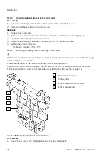
5.
8.
2.
Tighten screws.
–
Tightening torque: 3.0 Nm ± 10%
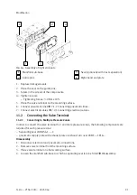
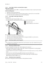
6. Place the valve terminal on the mounting surface.
7. Connect pneumatic lines
7.1.2 Connecting pneumatic lines.
Connect electrical cables:
–
Valve terminal
7.2.1 Connecting electrical cables.
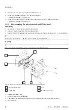
–
CPX terminal
è
Description of CPX system (CPX-SYS -...).
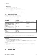
11.4
Adding Valve Positions
The smallest extension unit is a manifold sub-base:
–
For widths 18 mm and 26 mm with 2 valve positions
–
For widths 42 mm and 52 mm with 1 valve position
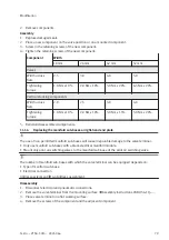
The following components are required to extend the valve terminal:
Components
Type code
Width 18 mm and 26 mm
Width 42 mm and 52 mm
Manifold sub-base that sup-
ports 1 solenoid coil per valve
position
VABV…-2T1
VABV…-T1
Manifold sub-base that sup-
ports 2 solenoid coils per valve
position
VABV…-2T2
VABV…-T2
Valve
VSVA-B-…
Cover plate
VABB… -WT
Tab. 56: Components required for valve position extension
If a manifold sub-base is added, the address assignment of all valves to the right of the added
manifold sub-base changes.
Disassembly
1. Remove valve terminal from the mounting surface.
2. Remove the manifold sub-base or pneumatic supply plate at the point at which the valve terminal
is extended
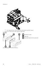
Assembly
1. Mount additional manifold sub-base and, if necessary, an additional pneumatic supply plate
Mount components
–
Vertical stacking components
–
Valves or cover plates
12
Technical data