


48
Festo — VTSA-F-CB — 2021-06a
Product overview
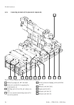
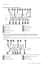
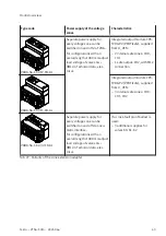
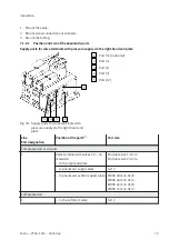
Explanations for example 3:
L
Duct separation 14
USW
Additional supply plate/exhaust plate with address extension for safe voltage zone
K
Duct separation 1/3/5/14 (note on necessary additional pilot air supply)
XC
Adapter plate with CPX pneumatic interface, for expansion by 3 safe internal zones (PROFI-
safe)
Z
External pilot air supply right-hand end plate
AB / CB Blanking plug
Tab. 30: Explanations for example 3
4.3
Operating modes
Depending on the types of valve used, the following valve terminal operating modes can be used:
–
Standard operation with one or more pressure zones
–
Reversible operation with compressed air supply via ports (3) and (5) and exhaust via port (1)
–
Low-pressure operation at 0 … 3 bar
–
Vacuum operation at –0.9 … 0 bar
4.3.1
Vacuum operation or low-pressure operation
The following valves with supply via port (1) are not suitable for vacuum or low pressure:
• Soft start valves
• Pilot air switching valves with internal pilot air supply
• 2x 3/2-way valves (ID codes H, QH, K, QK, N and QN)
The following requirements must be met to enable the valve terminal at the supply port (1) to operate
with vacuum or low pressure between –0.9 … 3.0 bar:
–
The pilot control is operated with an external pilot air supply.
–
Pressure zones with vacuum operation or low-pressure operation are equipped exclusively with the
following valves:
–
5/2-way valves, monostable (ID codes M, QM, O and QO)
–
5/2-way valves, bistable (ID codes D, QD, J and QJ)
–
5/3-way mid-position valves (ID codes B, QB, E, QE, G and QG)
4.3.2
Reverse operation
The supply duct and the exhaust air ducts are interchanged during reverse operation of the valve
terminal:
–
Compressed air supply via duct (3/5)
–
Exhausting via duct (1)