


84
Festo — VTSA-F-CB — 2021-06a
Modification
2.
3.
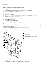
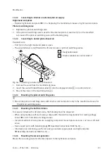
1. Place the vacuum generator on the manifold sub-base.
Tighten the retaining screws of the vacuum generator.
–
Tightening torque: 3.0 Nm ± 10%
Screw the manifold sub-base of the vacuum generator to other manifold sub-bases.
–
Tightening torque: 3.0 Nm ± 10%
11.3
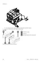
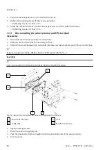
Disconnecting the valve terminal and CPX terminal
Disassembly
1. Disconnect electrical and pneumatic connections.
2. Remove valve terminal from the mounting surface.
3. Remove the screws between the pneumatic interface and the pneumatic part of the valve terminal.
Replace pneumatic interface
è
Description of CPX system (CPX-SYS -...).
Assembly
Only use pneumatic interfaces with a black electrical manifold module.
1
2
2
3
4
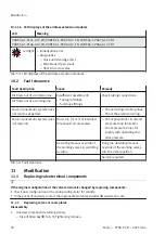
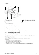
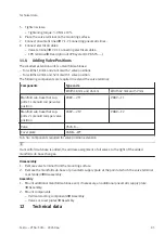
Fig. 47: Mount the manifold sub-base to the pneumatic interface
1
Pneumatic interface
2
Guide pins
3
Seal
4
Manifold sub-base
1. Replace damaged seals.
2. Place the seal on the guide pins.
3. Push the pneumatic interface together with the pneumatic part of the valve terminal.
4. Turn in screws.