


44
Festo — VTSA-F-CB — 2021-06a
Product overview
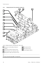
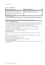
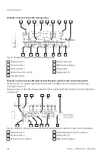
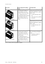
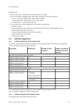
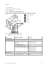
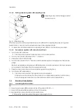
Example 1: pneumatic interface (PROFIsafe), 3 safe zones, 1 unsafe zone
5
3
1
S
CBUS
U
Elsen
U
Ven
Z0
Z1
Z2
Addr.
14
Q
0 addr.
A
-4 addr.
J
L
UW
+24 addr.
1
3
5
14
1−24
14
5
3
1
L
14
5
3
TL
YC
-2 addr.
14
1
CS
J
USW
+24 addr.
1
3
5
14
NBS
1−24
YB
-2 addr.
14
1
CS
J
PV
0 addr.
1
3
5
14
RC
+24 addr.
1−24
F43
GC
QP
+
CBUS
U
Elsen
U
Ven
Z0
Z1
Z2
Addr.
CBUS
U
Elsen
U
Ven
Z0
Z1
Z2
Addr.
Fig. 26: Example 1: pneumatic interface (PROFIsafe), 3 safe zones, 1 unsafe zone
Explanations for example 1:
F43
Bus node PROFINET
GC
Without node-specific connection technology
QP
Interlinking block with system supply, 7/8", 5-pin
RC
CPX pneumatic interface with 3 safe zones (PROFIsafe)
PV
Soft-start valve with separate voltage zone
YB
Manifold sub-base for switchable pilot air with second valve position
L
Duct separation 14
USW
Additional supply plate/exhaust plate with address extension for safe voltage zone
YC
Manifold sub-base for switchable pilot air with second valve position
TL
Duct separation 1/14
UW
Additional supply plate/exhaust plate with address extension for unsafe voltage zone
A
Manifold sub-base with 2 valve positions
Q
Vacuum generator
S
Internal pilot air supply of the right-hand end plate
Tab. 28: Explanations for example 1