VTSA-F-CB
Valve terminal
Manual
8142339
2021-06a
[8142341]
Страница 1: ...VTSA F CB Valve terminal Manual 8142339 2021 06a 8142341...
Страница 2: ...Translation of the original instructions PI PROFIBUS PROFINET PROFIsafe are registered trademarks of the respective trademark owners in certain countries...
Страница 3: ...mponents 34 4 1 7 Connection elements of the electrical components 35 4 1 8 Labelling elements 35 4 2 Function 35 4 2 1 Pneumatics functions 35 4 2 2 Electrical Functions 40 4 3 Operating modes 48 4 3...
Страница 4: ...exhaust plate or exhaust air cover 78 11 1 3 Replacing or adding vertical stacking components 78 11 1 4 Replacing the manifold sub bases or right hand end plate 79 11 2 Converting the Valve Terminal...
Страница 5: ...us node Commissioning parameterisa tion and diagnostics of the CPX terminal with the bus node Description CPX FVDA P2 Mode of operation installation and commissioning of the safe output module Assembl...
Страница 6: ...ered Comply with the handling specifications for electrostatically sensitive devices Observe further applicable documents 2 2 Intended use The VTSA F CB valve terminal is designed for switching and co...
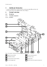
Страница 7: ...festo com catalogue 4 Product overview 4 1 Structure 4 1 1 Pneumatic components 4 1 1 1 Overview 1 2 3 4 5 6 7 8 9 10 13 11 12 Fig 1 Pneumatic components of the valve terminal 1 Right hand end plate 2...
Страница 8: ...be combined without adapter plate Some valve functions are only available in specific widths Identification of the valves An identification code is printed on the top of every valve The ID codes enab...
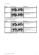
Страница 9: ...e monostable Pneumatic spring return O QO 5 2 way valve monostable Mechanical spring return SO 5 2 way valve monostable as plug in or via pilot valve with port pattern SF 5 2 way valve monostable Mech...
Страница 10: ...position port 2 pressurised port 4 exhausted switching posi tion 14 with memory function SD 5 3 way valve Mid position port 4 pressurised port 2 exhausted switching posi tion 14 with memory function S...
Страница 11: ...N QN 2 monostable 3 2 way valves Normally open Tab 7 Variants of the 2x 3 2 way valves Variants of the 2x 2 2 way valves ID code Circuit symbol Description VC 2 monostable 2 2 way valves Normally clo...
Страница 12: ...bistable valves VABV S4 2HS G18 CB 2T2 VABV S4 12HS G CB 2T2 VABV S2 1HS G38 CB T2 VABV S2 2S G12 CB T2 For monostable valves red solenoid coil contact VABV S4 1HS G14 CB 2T2 VABV S4 2HS G18 CB 2T1 VA...
Страница 13: ...aust air or via an exhaust air cover for common exhaust air Extension modules generate 24 additional valve addresses Variants of the supply plates Code Type code Description Exhaust air 3 5 common con...
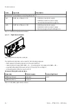
Страница 14: ...ab 11 Variants of extension modules 4 1 1 5 Right hand end plate Fig 4 Right hand end plate example The right hand end plate can be used for the following purposes Main supply of operating pressure to...
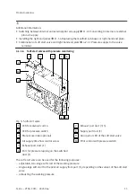
Страница 15: ...nitoring 1 2 3 4 5 6 7 8 9 10 Fig 5 Soft start valve 1 LED for solenoid coil 14 2 LED for pressure switch 3 Manual override optional 4 Air supply time flow control screw 5 Exhaust port duct 1 6 Port f...
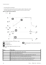
Страница 16: ...valve 1 Pilot pressure 2 Working pressure 3 Switching voltage of solenoid coil 12 and LED 4 Switching signal of the pressure switch and LED Time Description t0 Electrical control signal of the valve a...
Страница 17: ...n process takes place in 2 stages Duct 1 of the valve terminal is pressurised The pressurisation time t4 can be adjusted with the flow control screw on the soft start valve If the soft start valve is...
Страница 18: ...s ID code Circuit symbol Pilot air supply Manual override MO PM PMZQZ Pilot air from port 1 of the manifold sub base Self resetting PM PMZQX Pilot air from port 1 of the manifold sub base covered PN P...
Страница 19: ...r The pilot air duct is additionally exhausted unducted via the exhaust ports on both sides of the pilot air switching valve sensing of the exhausted status with a pressure switch in the pilot control...
Страница 20: ...8 Pressure regulator plates Fig 9 Pressure regulator plate A pressure regulator plate with adjustable pressure regulator can be installed between the manifold sub base and the valve in order to contro...
Страница 21: ...ulates the operating pressure in the duct 2 downstream from the direc tional solenoid valve The pressure regulator can only be adjusted in the switched state 10 ZH ZHY 6 Pressure regulator plate for p...
Страница 22: ...ZM 6 Pressure regulator plate for ports 2 and 4 reversible AB regulator ZE ZEY reversible valves required Regulates the pressure upstream of the directional solenoid valve The operating pressure is d...
Страница 23: ...ifold sub base 3 Intermediate plate 4 Duct 5 exhaust 5 Duct 1 working air 6 Duct 3 exhaust 7 Valve 8 Port 4 9 Port 2 10 B regulator 1 2 3 4 5 6 7 8 9 10 Fig 11 Pressure regulation with a reversible AB...
Страница 24: ...port 11 for sup plying individual operating pressure for a valve position duct 1 ZV VABF S P1A14 Plate with port 11 for sup plying individual operating pressure and individual pilot pressure for a va...
Страница 25: ...ressure supply to a single valve The ducts 1 and 14 are switched off simultaneously For example a vertical pressure shut off plate can be used to replace a valve without having to switch off the press...
Страница 26: ...ilot air Pressure reduction via duct 33 can be locked with key Tab 20 Variants of the vertical pressure shut off plates 4 1 1 12 Vacuum generator optional 1 2 3 4 5 6 7 8 9 10 11 Fig 15 Operating elem...
Страница 27: ...ating seal between manifold sub bases Pressure zones can be formed in the valve terminal to supply valves with different pressures The pressure zones are defined by separating seals between the manifo...
Страница 28: ...Separating seal Manifold sub base Exhaust ducts 3 and 5 white mark Pilot air duct 14 red mark Pilot air duct 14 Supply duct 1 green mark Pilot air duct 14 Supply duct 1 Exhaust ducts 3 and 5 Tab 21 I...
Страница 29: ...minal is electrically connected to the CPX terminal via the pneumatic interface Pneumatic interface The pneumatic interface connects the CPX terminal to the pneumatic part of the valve terminal The pn...
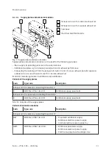
Страница 30: ...play elements of the pneumatic components 1 Common error LED address extension module 2 Common error LED for soft start valve 3 LED of solenoid coil 14 of special valves 4 LED pressure switch of the s...
Страница 31: ...Common error LED of the pneumatic inter face The LEDs and the meaning of the LED displays differ depending on the variant of the pneumatic interface Pneumatic interfaces VABA S6 1 X2 CB and VABA S6 1...
Страница 32: ...l elements of the pneumatic components 1 Cover caps for manual override 2 Adjusting knob 3 Operating pressure plug screw for one valve position 4 Adjusting screw for controlled flow 5 Air supply time...
Страница 33: ...1 1 3 Commissioning the pneumatic components with manual override MO The valve actuator combinations can be tested with the manual overrides 8 1 1 2 Testing valves and valve actuator combination The...
Страница 34: ...e pneumatic components 1 Pressure gauge port 90 rotatable 2 Ports 12 and 14 for supplying the external pilot air 3 Working ports 2 and 4 per valve posi tion 4 Port 1 separate operating pressure for on...
Страница 35: ...on elements of the electrical components 1 Service interface e g for operator unit 2 Fieldbus interface fieldbus specific 3 Earth terminal 4 Power supply connection 4 1 8 Labelling elements Labelling...
Страница 36: ...ht end plate VABE RZ feed at port 14 Pilot air switching valve VSVA BT M32CS2 supply at port 2 of the manifold sub base Supply component for the other pressure zones Soft start valve VABF P5A4S1 Pilot...
Страница 37: ...ting seals between the manifold sub bases 4 1 1 13 Separating seals for pressure zone formation Every pressure zone must be supplied with compressed air via a supply component Fig 23 Pressure free zon...
Страница 38: ...es with pilot air switching valve soft start valve and working valves Pressure zone 1 is supplied separately via soft start valve aJ for duct 1 and pilot air switching valve 9 for duct 14 Pressure zon...
Страница 39: ...hand end plate 6 for duct 1 1 2 3 4 5 6 7 8 9 Fig 25 Example 2 pressure zones with soft start valve and working valves 1 Pressure zone 1 2 Pressure zone 2 3 Exhaust port for duct 1 4 Separating seal f...
Страница 40: ...ches and the vacuum generators is supplied by the electronics power supply UEL SEN After switching off the load voltage supply the pressure switches continue to be supplied with voltage for the valves...
Страница 41: ...safe zone VABA S6 1 X1 3V CB VABA S6 1 X2 3V CB Separate power supply for each voltage zone possible If a cross fault proof ballast is used 3 additional supplies for valves X0 X1 X2 VABA S6 1 X2 F1 C...
Страница 42: ...nal power supply Separate power supply for every voltage zone can be switched on and off via FVDA Integrated output module CPX FVDA P2 PROFIsafe powered from external power supply 2 internal safe zone...
Страница 43: ...upplied from U_VEN 2 internal safe zones CH0 CH1 1 safe output CH2 with M12 connection VABA S6 1 X2 F1 CB AL Integrated output module CPX FVDA P2 PROFIsafe supplied from U_VEN 3 internal safe zones CH...
Страница 44: ...T GC Without node specific connection technology QP Interlinking block with system supply 7 8 5 pin RC CPX pneumatic interface with 3 safe zones PROFIsafe PV Soft start valve with separate voltage zon...
Страница 45: ...YB 2 addr 14 1 CS O YB 2 addr 14 1 CS J PV 0 addr 1 3 5 14 RC 24 addr 1 24 F43 GC QP CBUS UElsen UVen Z0 Z1 Z2 Addr CBUS UElsen UVen Z0 Z1 Z2 Addr Fig 27 Example 2 pneumatic interface PROFIsafe 6 safe...
Страница 46: ...address extension for safe voltage zone YB Manifold sub base for switchable pilot air with second valve position K Duct separation 1 3 5 14 XC Adapter plate with CPX pneumatic interface for expansion...
Страница 47: ...3 5 14 PV 0 addr 1 3 5 14 RB 24 addr 1 24 RB 24 addr 1 24 F43 GC QP CBUS UElsen UVen Z0 Z1 Z2 Addr CBUS UElsen UVen Z0 Z1 Z2 Addr Fig 28 Example 3 pneumatic interface 6 safe zones Explanations for ex...
Страница 48: ...operation at 0 9 0 bar 4 3 1 Vacuum operation or low pressure operation The following valves with supply via port 1 are not suitable for vacuum or low pressure Soft start valves Pilot air switching va...
Страница 49: ...working valves The pneumatic interface bundles the addresses of the working valves A total of up to 24 addresses can be controlled via the pneumatic interface Component Width mm Number of valve positi...
Страница 50: ...internal communication 2 The switching signal of the pressure switch can be used in an external controller via the M12 connection Tab 32 Address assignment of the special valves 4 4 3 Address assignm...
Страница 51: ...o the holder on the valve and snap it into place Disassembly Pull the identification holder out of the holder on the valve 7 Installation 7 1 Installation Pneumatics 7 1 1 Compressed air preparation 7...
Страница 52: ...risation and exhaust performance of the valve terminal e g with the following measures larger tubing diameters additional pressure feed via pneumatic supply plates Exhausting via pneumatic supply plat...
Страница 53: ...e terminals with pressure supply via the right hand end plate 1 Port 14 optional 2 Port 5 3 Port 1 4 Port 3 5 Port 12 Line Port designation Position of the ports1 Port size Compressed air or vacuum 1...
Страница 54: ...lot control external pilot air supply 142 Valve terminal with valves 18 52 mm wide in the right end plate G1 4 12 in the manifold sub bases of the pilot air switching valves G1 8 Working air or vacuum...
Страница 55: ...atic lines 1 2 3 4 5 5 5 6 6 Fig 31 Common pneumatic lines with check valves 1 Valve terminal 1 2 Central pilot air exhaust line 3 Central exhaust line 3 5 4 Valve terminal 2 5 Exhaust lines 3 5 of th...
Страница 56: ...nal 2 Mount right hand end plate VABE R The internally branched pilot air is supplied to the valves only via duct 14 End plate VABE RZ for external pilot air supply 1 2 Fig 33 Right hand end plate VAB...
Страница 57: ...with the releasing tool QSO from Festo 3 Remove the tubing from the fitting 7 1 3 Setting pressure regulator Restrictions for AB pressure regulators The pressure regulator restricts the exhaust flow T...
Страница 58: ...Press the rotary knob into the freewheel level 3 The rotary knob can be turned without changing the controlled variable Turn the rotary knob lengthwise to the pressure regulator plate 3 Press the rot...
Страница 59: ...4 Turn the rotary knob in the direction until the desired pressure is displayed on the pressure gauge Maintain permissible working pressure Rating plate Correctly pressurised the input pressure p1 is...
Страница 60: ...erators is provided by the operating power supply UEL SEN After switching off the load voltage supply the pressure switches continue to be supplied with voltage for the valves of the CPX terminal UVAL...
Страница 61: ...1 X2 F2 CB Zone extension adapter VABA S6 1 X2 F2 CB2 AL and VABA S6 1 X2 F2 CB AL Pin allocation Bushing X1 1 0 V CH21 2 24 V CH21 3 F DO M CH22 4 F DO P CH22 5 Functional earth 1 Unswitched voltage...
Страница 62: ...ble with large cross section Further information Description of the CPX system CPX SYS 8 Commissioning 8 1 Commissioning of the Pneumatic Components 8 1 1 Testing pneumatic components 8 1 1 1 Determin...
Страница 63: ...inant in this case Reset the electrical signal before operating the manual override 1 Switch on the compressed air supply 2 Reset electrical signals on controlled valves 3 Test the functioning and eff...
Страница 64: ...unction of the manual override can be modified to non detenting actua tion only by mounting the MO cover cap Detenting actuation manual reset VSVA D 1 Use a screwdriver to push in the plunger of the M...
Страница 65: ...mains in switching position 3 Release the plunger Spring returns the MO plunger to its initial position Valve reverts to normal position not for bistable 5 2 way valves with ID codes D and J Detenting...
Страница 66: ...lves with ID codes D and J Detenting actuation manual reset VSVA YE 1 Press MO down to the stop The valve moves to switching position 2 Pull MO up to the stop Valve reverts to normal position Detentin...
Страница 67: ...2 Cover cap for MO concealed 3 Cover cap for MO non detenting Prerequisite the MO is in normal position Align the cover cap and clip the snap hooks into the recesses of the MO The cover cap is mounted...
Страница 68: ...PA VSVA BT M32CS1 MYE A2 1T5L PA VSVA BT M32CS2 MS A2 1T5L PA VSVA BT M32CS1 MS A2 1T5L PA Byte Bit Description Process input data 0 7 1 reserved 0 0 duct 14 is pressurised 1 duct 14 is exhausted Proc...
Страница 69: ...des VABA S6 1 X1 CB VABA S6 1 X2 CB VABA S6 1 X1 3V CB VABA S6 1 X2 3V CB VABA S6 1 X2 F1 CB VABA S6 1 X2 F2 CB VABF S6 1 P8A7 G12 CB VABF S6 1 P8A7 G12 CB1 VABF S6 1 P8A6 G12 CB VABF S6 1 P8A6 G12 CB...
Страница 70: ...very additional bus device is assigned the next highest module number Working valves are not assigned a module number Module numbering Type code Number of bus stations Number of assigned module number...
Страница 71: ...14 A VABF S4 2 V2B1 G38 CB VH 14 AP VABF S4 2 V2B1 G38 CB VL 14 AP VABF S4 2 V2B1 G38 CB VH 20 A VABF S4 2 V2B1 G38 CB VL 20 A VABF S4 2 V2B1 G38 CB VH 30 A VABF S4 2 V2B1 G38 CB VH 20 AP VABF S4 2 V...
Страница 72: ...ostics The parameter Wire break diagnostics defines whether the diagnostics for the input signals must be activated or deactivated with regard to a shortfall of the input current When the diagnostics...
Страница 73: ...scent current monitoring of the valve solenoid coils open load only with logic 0 active Check valves as well as their correct assembly and electrical connection Replace valve if necessary if necessary...
Страница 74: ...Tab 49 LED displays of the valves 10 1 1 3 LED displays of the soft start valves LED Meaning Possible errors Solenoid coil LED 14 off Signal not pending logic 0 yellow light Signal is pending logic 1...
Страница 75: ...Compressed air supply defective Pilot exhaust air blocked Service required LED of the pressure switch green light Duct 14 is exhausted Tab 51 LED displays of the pilot air switching valves 10 1 1 5 LE...
Страница 76: ...ng of tubing lines Check the electrical wiring Valve or pneumatic system does not respond Ducts 3 5 or 12 intended for exhaust air are sealed Check pneumatic circuit and pressure zone formation Check...
Страница 77: ...crews Tightening torques Tab 55 Tightening torques Width Valve Tightening torque of screw Spanner size for internal hexagon 18 mm VSVA A2 1 0 Nm 10 2 5 26 mm VSVA A1 2 0 Nm 10 3 42 mm VSVA D1 3 0 Nm 2...
Страница 78: ...ing screws Tightening torque 2 2 Nm 10 11 1 3 Replacing or adding vertical stacking components If vibrations and shocks with severity level 2 are expected install a maximum of one vertical stacking co...
Страница 79: ...s 11 1 4 Replacing the manifold sub bases or right hand end plate The use of non permitted manifold sub bases will cause irreparable damage to the valve terminal Only use manifold sub bases with a bla...
Страница 80: ...mponents are only held together by the electrical manifold module 5 Remove the component from the adjacent components Assembly 1 2 2 3 1 Fig 43 Assembly of manifold sub bases 1 Manifold sub base 2 Gui...
Страница 81: ...c lines 7 Connect electrical cables 7 2 1 Connecting electrical cables 11 2 Converting the Valve Terminal 11 2 1 Converting to Multiple Pressure Zones In order to convert the valve terminal to 2 and m...
Страница 82: ...5 Identification of the separating seal 6 Pneumatic supply plate with port 1 for compressed air supply to the pressure zone 2 7 Pneumatic supply plate with port 1 for compressed air supply to the pres...
Страница 83: ...d sub base 2 Insert the seal with identification label 1 into the display window 2 on control side 12 3 Mount the valve on the manifold sub base 11 2 4 Mounting the pilot air switching valve Mount the...
Страница 84: ...onnections 2 Remove valve terminal from the mounting surface 3 Remove the screws between the pneumatic interface and the pneumatic part of the valve terminal Replace pneumatic interface Description of...
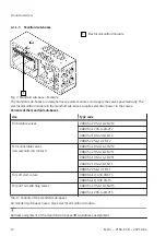
Страница 85: ...26 mm Width 42 mm and 52 mm Manifold sub base that sup ports 1 solenoid coil per valve position VABV 2T1 VABV T1 Manifold sub base that sup ports 2 solenoid coils per valve position VABV 2T2 VABV T2 V...
Страница 86: ...ss CRC 0 Mounting position Any for wall mounting and support system mounting Resistance to vibration shock resistance See assembly instructions for terminal CPX valve terminal VTSA 1 1 Applicable docu...
Страница 87: ...idth 42 mm for one valve position Tab 58 Weight Materials Die cast aluminium aluminium steel brass polyamide nitrile rubber elastomer polyoxymethylene Tab 59 Materials Tightening torques Width 18 mm 2...
Страница 88: ...62 Manual override 12 3 2 Operating pressure pilot pressure Operating pressure pilot pressure of valves Soft start valves Pilot air not from connection 1 of manifold sub base bar 2 10 Pilot air from p...
Страница 89: ...QN Fig 48 Required pilot pressure p12 14 as a function of the operating pressure p1 of the external pilot air supply 5 2 way valves ID codes D J M O QD QJ QM QO and 5 3 way valves ID codes B E G QB Q...
Страница 90: ...0 1 10 FI 2 6 1 6 ZE Pressure regulator plate for ports 2 and 4 reversible AB regulator 0 5 10 ZJ 0 5 6 ZK Pressure regulator plate for port 4 reversible A regu lator 0 5 10 ZM 0 5 6 ZL Pressure regul...
Страница 91: ...24 SE Control side 14 30 23 SB Control side 12 12 Control side 14 9 Control side 12 28 SD 1 Method of measurement 0 10 in accordance with FN 942032 Tab 65 VSVA B at 24 V DC width 18 mm VSVA B at 24 V...
Страница 92: ...ement 0 10 in accordance with FN 942032 Tab 66 VSVA B at 24 V DC width 26 mm VSVA B at 24 V DC width 42 mm ID code Valve assembly Valve switching times ms 1 On Reverse Off VC VV 2x 2 2 way valve 20 38...
Страница 93: ...2 Tab 68 VSVA B at 24 V DC width 52 mm Soft start valve Valve switching times ms On Off VABF S6 1 P5A4 20 20 85 20 Tab 69 Soft start valves VABF S6 1 Pilot air switching valve Valve switching times ms...
Страница 94: ...position 460 Mid position 350 SB Switching position 440 Mid position 400 SD Switching position 1 2 430 Switching position 4 5 450 Mid position 1 4 340 Mid position 2 3 360 Tab 71 Standard nominal flo...
Страница 95: ...VV 2x 2 2 way valve 1500 H K N 2x 3 2 way valve 1300 QH QK QN 1100 D J M O 5 2 way valve 1860 QD QJ QM QO 1300 B pressurised 5 3 way mid position valve Switching position 1690 Mid position 830 E exhau...
Страница 96: ...tion 900 QB pressurised Switching position 2700 Mid position 1700 QE exhausted QG closed Tab 74 Standard nominal flow rate valves VSVA B width 52 mm Soft start valve Standard nominal flow rate l min P...
Страница 97: ...ction of output pressure p2 for port 1 input pressure 6 bar set regulated pressure 6 bar 1 Width 18 mm 2 Width 26 mm Pressure regulator plates P regulator widths 18 mm and 26 mm at 6 bar 1 2 Fig 51 Fl...
Страница 98: ...bar Fig 52 Flow rate qn as a function of output pressure p2 for port 1 input pressure 10 bar set regulated pressure 6 bar Pressure regulator plates P regulator width 52 mm at 10 bar Fig 53 Flow rate q...
Страница 99: ...tput pressure p2 for port 2 4 or ports 4 2 input pressure 6 bar set regulated pressure 6 bar 1 Width 18 mm 2 Width 26 mm Pressure regulator plates AB regulator widths 18 mm and 26 mm at 10 bar 1 2 Fig...
Страница 100: ...rate qn as a function of output pressure p2 for port 2 4 or ports 4 2 input pressure 10 bar set regulated pressure 6 bar Pressure regulator plates AB regulator width 52 at 10 bar Fig 57 Flow rate qn...
Страница 101: ...lator plates reversible for ports 4 2 reversible input pressure 6 bar set regulated pressure 6 bar 1 Width 18 mm 2 Width 26 mm Pressure regulator plates AB regulator widths 18 mm and 26 mm at 10 bar 1...
Страница 102: ...pressure regulator plates AB regulator plates reversible for ports 4 2 input pressure 10 bar set regulated pressure 6 bar Pressure regulator plate AB regulator width 52 mm at 10 bar Fig 61 Flow rate...
Страница 103: ...d 26 mm 1 2 Fig 62 Flow rate qn as a function of the revolutions n of the adjusting screw 1 Width 18 mm 2 Width 26 mm Throttle plates width 42 mm 1 2 Fig 63 Flow rate qn as a function of the revolutio...
Страница 104: ...mm Load voltage supply for valves DC UVAL V 24 10 25 26 4 for configurations with an overall length of 1000 mm Diagnostic message undervoltage UOFF load voltage outside the functional range V 20 6 20...
Страница 105: ...rom UVAL Valves with CPX FVDA P2 mA Typically 22 from UVAL Intrinsic current consumption VABA S6 1 X2 CB2 AL at 24 V DC Electronics without CPX FVDA P2 mA Typically 4 from UEL SEN Electronics with CPX...
Страница 106: ...2021 all rights reserved to Festo SE Co KG Copyright Festo SE Co KG 73734 Esslingen Ruiter Stra e 82 Deutschland Phone 49 711 347 0 Internet www festo com...