8
charger will be in the stand by position.
②
Insert the battery in the battery charger
considering the polarity, and the charging will
be started immediately.
③
When the battery working time is remarkably
short despite full charging, the life of the
battery may be over. Replace the battery
immediately.
times of charging and discharging. Charge
and discharge the battery, which is not
used for a long time, for two to three times
to function well.
Take care not to short-circuit the terminal
of the battery. The short-circuit of the
doing a serious personal injury.
2) Charging process
charger. Otherwise battery and charger
charging error or overheat.
①
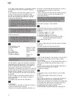
Charging indication
Green Blinks : Before charging
Red Lights : While charging
Green Lights : Charging completed
Red Blink : Overheat stand by
(Battery overheated)
Yellow Blinks : Charging impossible
Be sure to unplug the charger after
②
If charging of the heated battery is attempted
immediately after it has been used or charged,
indicator blinks in red (overheat stand by).
After the cooling, indication changes to red
glowing and charging begins.
③
This charger detects charging status of the
battery and always keeps the battery in full
charge state.
3) Installing and removing battery
①
Installing.
- Set the rotational direction switch at centre
position (locked state).
- Insert the charged battery into the slot
below the handle until the battery securely
latched with a click.
②
Removing.
- Push the battery button once and take it
out to remove it.
Always set the rotational direction switch at
centre position when inserting the battery
or changing, carrying or storing the tool.
4) Charge state of the battery
Pulling the switch trigger will turn on the
battery level indicator for about 2 seconds.
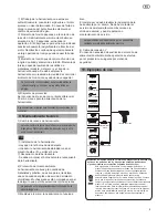
1 = Battery 70 - 100% charged
2 = Battery 30 - 69% charged
3 = Battery less than 30% charged
5) Work light
Pulling the switch trigger will turn on
the LED light
6) Reversing the Rotation Direction
Reversing the rotation direction must be done
direction during operation may damage the tool
L (Left rotation) : Counterclockwise direction
(for loosening of bolt, nut, screw)
R (right rotation) : Clockwise direction
(for fastening of bolt, nut, screw)
Neutral : Rotation lock (for changing the bit)
7) Adjusting the Speed
RPM control with variable switch
The switch has speed control function.
Pull the switch a little to operate at slow smooth
speed and pull more for speedier operation. By
pulling the switch, RPM can be adjusted from
zero to maximum rotation.
8) Working Instructions
①
Impact operation automatically starts when
the load is higher than certain level.
Under no load condition, pushing the switch
will only cause adjustment of RPM.
②
Fastening torque depends on the duration of
impact operation. Generally, maximum torque
is achieved after 3 to 10 seconds of impact
operation. Operating longer will result in only a
limited amount of torque increase. Operating
the impact for an unnecessarily long time can
cause the motor to burn and damaged.
4
6
7
8
9
5
Содержание SD10,8IL
Страница 1: ...SD10 8IL...
Страница 2: ...2 ILLUSTRATIONS 1 2 3 4 5 6 7 10 8 9...
Страница 11: ...2 Planos 1 2 3 4 5 6 7 10 8 9...
Страница 19: ...SD10 8IL...
Страница 20: ...2 Zeichnungen 1 2 3 4 5 6 7 10 8 9...
Страница 29: ...SD10 8IL VISSEUSE CHOC SANS FIL...
Страница 30: ...2 Dessins techniques 1 2 3 4 5 6 7 10 8 9...
Страница 39: ...SD10 8IL...
Страница 40: ...2 Disegni 1 2 3 4 5 6 7 10 8 9...
Страница 48: ...SD10 8IL...
Страница 49: ...2 1 2 3 4 5 6 7 10 8 9...
Страница 50: ...3 1 3 2 5 3 6 4 6 5 7 6 7 7 8 8 10 1 1 b 2 b d f 3...
Страница 51: ...4 b d f g 4 b d f g 5 b d e f...
Страница 54: ...7 5 1 SD10 8IL 1 1 2 3 4 5 6 7 FL10813 2 F108 3 2 1 2 0 40 80 3 3 6 1 2 3 4...
Страница 56: ...9 5 7 6 8 4 L R 7 9 1 8 1 2 2 2 3 10 3...
Страница 57: ...10 8 1 10 1 2 2 Felisatti Felisatti Y 3 40 80 4 5...
Страница 58: ......
Страница 59: ......


