


Additional Modes
28
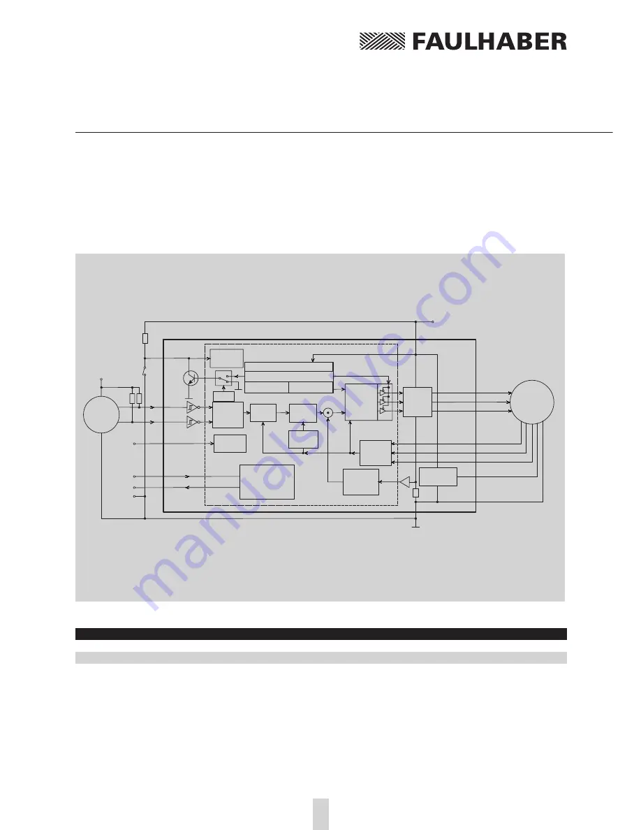
Gearing Mode
In Gearing Mode it is possible to connect an external encoder to provide the command position
value.
PI-Speed
Controller
MOSFET
Power
Amplifier
EC-Motor
Armature
Position
Calculation
Phase A
Phase B
Phase C
Hall Sensor A
Hall Sensor B
Hall Sensor C
Speed
Calculation
I
2
t - Current
Limiting
R
S
GND
V7
Microcontroller
RS-232
Communication
and Configurations
Module
+ 24V DC
V6
U
B
PC TXD
PC RXD
GND
n
act
V2
V1
RXD
TXD
I
act
Position
Controller
RS-232
Interface
3 Phase
PWM
Sine Wave
Commutator
ϕ
(t)
n
com
∆ϕ
U
a
Protection:
Current Limit
Overtemperature
Overvoltage
Undervoltage
5V- Regulator
VCC
Signal GND
Evaluation
Input 3
Input 3
V8
M8
M7
M1
M2
M5
M6
M3
M4
brown
orange
yellow
green
blue
grey
red
black
+5V
V4
Fault
Output
V5
V3
Command
Position
Calculation
10k
E
xam
ple:
Lim
it S
w
itch
REFIN
Evaluation
Limit Switch
Analog
Input
AGND
Encoder
VDD
ChA
ChB
2,7k
2,7k
Diagram 9: Gearing Mode with a reference point at the Fault Pin
The reduction ratio is calculated just as in Stepper Motor Mode.
Command
Function
Description
Example
GEARMOD *) Gearing Mode
Switches to gearing mode
GEARMOD
The direction of rotation can be programmed with the ADR (rotate right) and ADL (rotate left)
commands or it can be set by an external signal at the Fault Pin (DIRIN command).
In gearing mode the
AC
- and
SP
-values (see Position Control) are also applicable making soft
acceleration and braking possible.
The command
APL1
applies position limits (LL-Command) to the sequence.
With the command
APL0
the position limits will be ignored (Default setting).
Содержание MCDC2805 series
Страница 58: ...58 Notes ...
Страница 59: ...59 Notes ...