Operation - Pull Type 7420, 8420
33
Reducing The PTO Driveline Length
Stop the engine and leave the operator’s position
(See “Leaving The Operator’s Position” in the
Operation section). Make sure the PTO driveline and
all rotating components have come to a complete
stop before leaving the operator’s position.
WARNING
AVOID INJURY OR DEATH
•
Do NOT exceed the rated implement PTO speed.
•
Stay clear of rotating driveline.
•
Keep bystanders away.
•
Keep hands, feet, clothing and long hair away.
•
Keep PTO shields and all guards in place.
•
Disengage PTO, move the tractor controls to
the Neutral position, stop the engine and make
sure all rotating components are stopped before
leaving the operator’s position.
•
Do NOT service the tractor or implement with
the PTO engaged.
•
Do NOT service the implement in a raised
position unless properly blocked and with all
rotating components stopped.
•
Disengage PTO for road travel.
Remove the PTO driveline from the tractor and
place in storage position (if equipped).
Enter the operator’s position (See “Entering The
Operator’s Position” in the Operation section).
Start the engine.
Raise or lower the three-point implement to get
the shortest distance between the tractor PTO shaft
and three-point implement gearbox PTO shaft.
Stop the engine and leave the operator’s position.
Pull the PTO driveline apart and reinstall each
individual section; one half to the tractor PTO shaft
and one half to the implement gearbox PTO shaft.
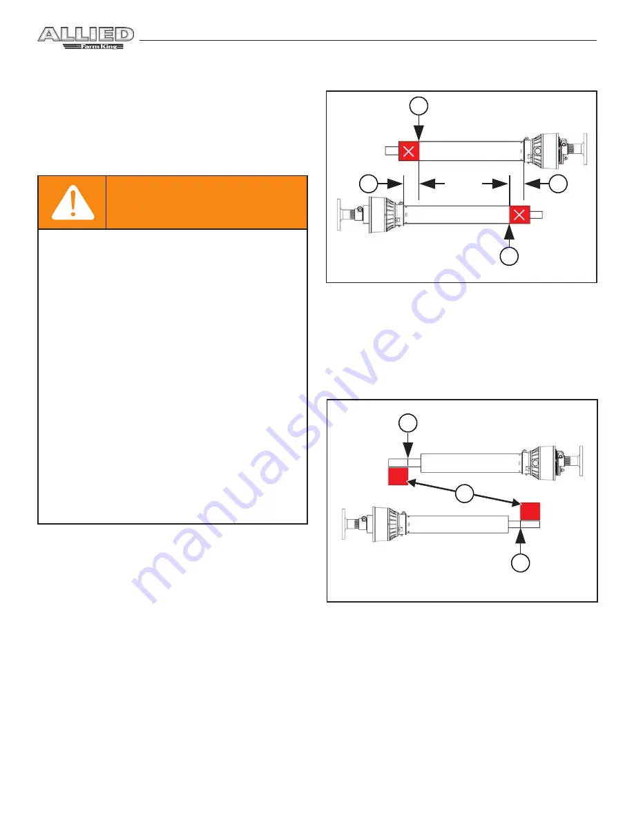
Figure 19
1. Hold PTO driveline sections parallel to one another
and measure back 2 in. (50.8 mm) (Item 1)
[Figure
19]
from the yoke of each section and place mark on
opposite section. Cut the plastic shield at this length
(Item 2)
[Figure 19].
Figure 20
2. Using the plastic guard lengths that were cut off in
[Figure 19]
, align the cut off lengths (Item 1)
[Figure
20]
with the end of the inner & outer shafts. Place a
mark (Item 2)
[Figure 20]
on the inner & outer shafts
and cut the inner & outer shafts off at this length.
3. Round off all sharp edges and debur.
4. Thoroughly grease and install the PTO driveline
halves together.
5. Recheck for proper operation.
TRACTOR
PTO SHAFT
TRACTOR
PTO SHAFT
IMPLEMENT
PTO SHAFT
IMPLEMENT
PTO SHAFT
2
2
2
1
1
2
1
Содержание ALLIED 7420
Страница 1: ...072017 FK410 OPERATOR AND PARTS MANUAL PullType Snowblower Model 7420 8420 ...
Страница 2: ......
Страница 6: ...Warranty Registration Form PullType 7420 8420 2 ...
Страница 8: ...Introduction PullType 7420 8420 4 ...
Страница 12: ...Introduction PullType 7420 8420 8 ...
Страница 14: ...Safety PullType 7420 8420 10 ...
Страница 24: ...Assembly PullType 7420 8420 20 ...
Страница 30: ...Assembly PullType 7420 8420 26 ...
Страница 32: ...Operation PullType 7420 8420 28 ...
Страница 44: ...Maintenance PullType 7420 8420 40 ...
Страница 50: ...Maintenance PullType 7420 8420 46 ...
Страница 52: ...Parts Identification PullType 7420 8420 48 ...
Страница 62: ...Parts Identification PullType 7420 8420 58 Spout Rotator Hydraulic 1 2 10 9 8 7 4 5 6 3 11 ...
Страница 68: ...Parts Identification PullType 7420 8420 64 PTO Shaft F1732 7 6 2 4 5 3 1 10 11 9 3 8 ...
Страница 72: ...Specifications And Shipping Kit Numbers PullType 7420 8420 68 ...
Страница 74: ...Specifications And Shipping Kit Numbers PullType 7420 8420 70 HardwareTorque Values Metric Chart ...
Страница 75: ...Specifications And Shipping Kit Numbers PullType 7420 8420 71 Imperial Chart ...
Страница 76: ...Specifications And Shipping Kit Numbers PullType 7420 8420 72 ...
Страница 78: ...Warranty PullType 7420 8420 74 ...
Страница 81: ......


