


OPTION
DESCRIPTION
Active Faults
Information on all active faults
Air Flow
Flow change percentage for all four channels.
Functions
Enter to select, test, isolate, disable, reset
baseling functions
Event History
View event history
Configuration
View current configuration of the device
LCD Settings
Adjust language setting for LCD, contrast
Message Log
View message log history
Set Time
Set local time on device
Diagnostics
View diagnostics
ACTIVE FAULTS SCREEN
Only the highest priority fault is shown on the home screen, but it is possible
to for a device to have more than one fault. These faults can be seen with the
Active Faults screen. The screen displays all active faults from highest to low-
est priority. The priority fault level is as follows:
PRIORITY
FAULT
NOTES
1
Disable
2
Isolate
3
Configuration
5
Sensor
6
Aspirator
7
Internal
Internal HW/Sw failure
8
Low Voltage
9
High Flow ( Ch. 1-4)
10
LowFlow ( Ch. 1- 4)
11
Filter
12
External Monitor
Conventional devices only
13
Time
AIR FLOW SCREEN
The Air Flow screen shows the level of air flow change as a percentage for
each channel and the programmed boundary level. There is also a bar graph
to for each channel to provide a visual indication of how close the flow is to
a boundary level. If not all channels are being used the screen will display
‘Disabled’ next to the channel.
Air Flow
1
-13%
-2%
-1%
-1%
2
3
4
Enter Password
* * 4 _
ASP111-00
ASP123-00
FIGURE 12. AIR FLOW SCREEN
FIGURE 13. FUNCTIONS MENU SCREEN
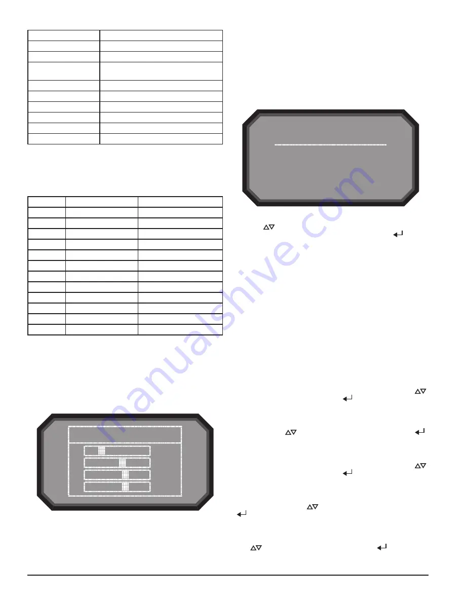
FUNCTIONS MENU SCREEN
The Functions menu screen is used to change the device’s state or activate
test mode. Because this menu allows the user to change the device out of its
normal operating state there is an optional lock out feature for this menu. The
lockout requires a 4-digit passcode to enter the functions menu – this pass-
code is set using the PipeIQ Software. When the functions menu is accessed
from the main menu screen with the lock feature enabled, the enter password
screen will be displayed.
The scroll (
) keys are used to increment or decrement the number for
the digit the cursor is on. To enter the number use the select (
) key and
the cursor will advance to the next digit. When the last digit is entered the
Functions menu will be displayed if the password was entered correctly. If
the password does not match the display will show Password Invalid for 3
seconds and then return to the home screen.
From the functions menu the following options are available:
• Isolate
• Disable
• Reset
• Reset Baselines
• Test
• Sounder Test
• Reset IP Network
ISOLATE SCREEN
The Isolate function will set the device into the isolate mode. When this func-
tion is selected from the functions menu the device will display that Isolate
mode will be activated and will ask for a confirmation. Use the scroll (
)
keys to select cancel or ok and then select (
) key to confirm the selection.
DISABLE SCREEN
The Disable function will set the device into the Disable mode. When this
function is selected from the functions menu the device will ask for confirma-
tion. Use the scroll (
) keys to select cancel or ok and then select (
)
key to confirm the selection.
RESET SCREEN
The Reset function will reset the device. When this function is selected from
the functions menu the device will ask for confirmation. Use the scroll (
)
keys to select cancel or ok and then select (
) key to confirm the selection.
RESET BASELINES SCREEN
The Reset Baseline function will set the device into the Reset Baseline mode.
When this function is selected from the functions menu the device will ask for
confirmation. Use the scroll (
) keys to select cancel or ok and then select
(
) key to confirm the selection.
TEST SCREEN
The Test function will set the device into the Test mode. When this function is
selected from the functions menu the device will ask for confirmation. Use the
scroll (
) keys to select cancel or ok and then select (
) key to confirm
the selection.
8 ASUG56601
firealarmresources.com