


BACKLIGHT SCREEN
The Backlight screen is used to adjust the brightness of the backlight. Use the
scroll (
) keys to increase and decrease the backlight brightness.
CONTRAST SCREEN
The Contrast screen is used to adjust the contrast of the text. Use the scroll
(
) keys to increase and decrease the contrast.
MESSAGE LOG SCREEN
The Message Log history can be viewed through the LCD screen. The Message
Log screen displays the message number currently being displayed, the total
number of messages available, and the message. Use the scroll (
) keys to
advance up or down through the message logs.
SET TIME SCREEN
The Set Time screen allows the user to set the time and date of the device.
This feature can be locked out and require the user to enter a 4 digit access
code to enter the set time menu. When first entering the screen the hour time
will be highlighted. Use the scroll (
) keys to change the value. When the
desired hour is selected use the select (
) key to set the hour and the cursor
will advance to the minutes. As each field is set the cursor will progress until
it reaches the end. After the year is set the cursor will cycle back to the hour.
SPECIAL MODE SCREENS
Special mode screens are displayed temporarily when a specific action or
unique operation mode is currently active.
INITIALIZATION SCREEN
The Initialization screen appears when the device is first powering up. It will
last for 10 to 15 seconds when the device is first powered on.
BASELINING SCREEN
The baselining screen appears for the first 5 minutes after the device has ini-
tialized and indicates that the active air channel and filter flow levels are cur-
rently being observed to determine the baseline. This screen will also appear
when a reset baseline is done.
FIRMWARE UPGRADE SCREEN
When a firmware upgrade is in progress the LCD will display the Firmware
Upgrade in progress screen with a progress bar, and a warning to not remove
power.
MODES OF OPERATION
INITIALIZATION
When the FAAST system is initially powered up it is not configured, a fault in-
dication is set with the General Fault LED and the LCD home screen displaying
a configuration fault. This will indicate that the device has not had its initial
configuration loaded and will remain in this fault state until a configuration
is sent to the device. Once the device is configured, or upon reconfiguration,
the device will perform an initialization. This initialization will set the air
flow baseline and the filter clogged baseline. It is important that the system
is connected properly to the pipe network and the filter is installed properly
when the device is initialized as these baselines will be used to indicate when
a fault should occur. During the initialization period the device will operate as
normal with the exception that flow and filter faults will not be indicated until
the baseline is set. Establishing the baseline takes approximately five minutes.
CONFIGURATION OVERVIEW
FAAST XT is configured using PipeIQ. Data is sent via a built in Ethernet con-
nection or through the USB interface located on the front of the device. The
device will receive the configuration and will perform a validation before the
configuration becomes active. After validation of the data the device will per-
form an initialization with the new configuration. If there is a problem with
the configuration data the device will indicate a Configuration Fault on the
user interface and will set the Urgent Fault relay. The device will require a new
configuration before operating properly.
FAN SPEED CONFIGURATION
The device is capable of running at 3 different fan speeds to help power con-
sumption for the area of coverage. To minimize power the lowest fan speed
should be chosen. The fan speed directly affects the performance of the de-
vice. Therefore, when creating a pipe layout the calculations that are per-
formed are based on the fan setting. If the fan setting is changed on the device
at a later date the pipe system must be re-verified.
ALARM AND RELAY CONFIGURATION
Alarm thresholds are set to default levels when shipped, but are configurable.
Each Alarm level has its own set of form C relay contacts. As the particulate
level crosses the threshold for the alarm level the corresponding indicator will
illuminate and the relay will activate. The Alarm thresholds and their associ-
ated relay outputs are configurable for latching or non-latching operation For
each alarm level, there is a configurable delay from 0 to 60 seconds. Configu-
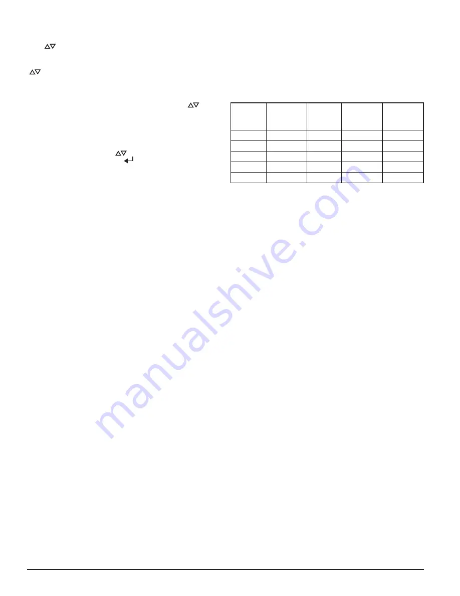
rable thresholds for each alarm level are as follows:
TABLE 5. PROGRAMMABLE ALARM LEVELS
ALARM
LEVEL
DEFAULT
THRESHOLD
%OBS/FT
PROG.
RANGE %
OBS/FT
DEFAULT
THRESHOLD
%OBS/M
PROG.
RANGE
%OBS/M
Alert
0.012
0.00046 - 6.0 0.0396
0.0015 - 20.0
Action1
0.050
0.00046 - 6.0 0.165
0.0015 - 20.0
Action2
0.100
0.00046 - 6.0 0.33
0.0015 - 20.0
Fire1
0.250
0.00046 - 6.0 0.825
0.0015 - 20.0
Fire2
0.500
0.00046 - 6.0 1.65
0.0015 - 20.0
AUDIBLE INDICATOR CONFIGURATION
There is a built audible indicator on the FAAST 9400X which gives the op-
tion to include a supplementary audible indication of alarms and faults. The
settings are configurable using the PipeIQ software. The sounder is capable
of generating a pulsed or continuous tone. Both the alarm and fault can be
selected to do either tone.
FAILURE OF CONFIGURATION VALIDATION
If configuration validation fails during the configuration process, the software
configuration tool will indicate a failure and the device will illuminate the
fault indicator. Subsequently, the device will not accept any of the data as
valid and will revert back to its previous configuration.
POWER GLITCH DURING CONFIGURATION
During an upload of configuration data, the device will keep the last known
good configuration in memory until a complete validation is done on the new
configuration data. This prevents device corruption in the event of a power
loss or network failure. When power is restored the device will initialize with
the last known good configuration. The device will also indicate a Configura-
tion Fault on the user interface and set the Minor Fault Relay. This will only
occur once. When the next Reset or Power on Reset is performed the device
will continue to use the last known good configuration.
NORMAL
In Normal operating mode the FAAST XT displays the air flow and current
particulate levels on the user display. The time, date, address, and current
obscuration is shown on the LCD. The particulate level is compared to the
threshold levels programmed into the device and will activate the appropri-
ate alarm as the particulate exceeds that threshold. If any fault occurs it will
activate the fault LED and display the type on the LCD as well as set the cor-
responding relay.
TEST
Test mode is initiated through the PipeIQ Live View tab or through the LCD in-
terface. Test mode will simulate a fire condition by activating all ten segments
in the Particulate Level display and each segment in the Alarm display. Each
corresponding alarm relay will also activate after any programmed delay asso-
ciated with that relay. To remove the device from test, a RESET must be done.
SOUNDER TEST
The sounder test function can be accessed via the LCD user interface. Upon
initiation, the device will exercise the selected sounder tones for fault and
alarm conditions. The sounder may be configured to give continuous or pulsed
tones for alarm and fault conditions. Tones may be selected using PipeIQ.
RESET
Reset mode is initiated through the PipeIQ mimic view or through the LCD
interface. When RESET is activated all relays will be reset. It will then enter
Normal mode operation. If any fault or alarm states remain the device will re-
activate the state automatically.
10 ASUG56601
firealarmresources.com