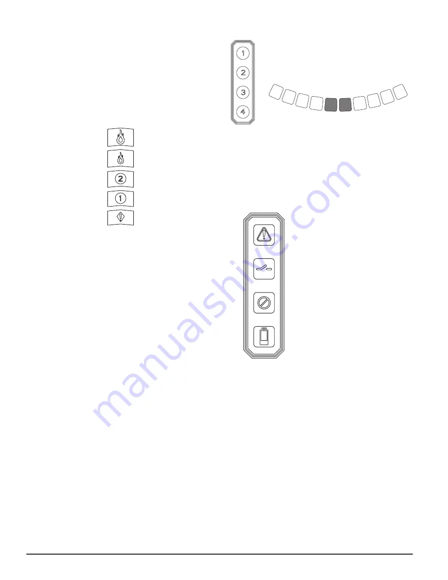
background image

ALARM LEVEL DISPLAY

The alarm level display consists of five red LEDs that correspond to the cur-
rent alarm level, shown in Figure 7. These LEDs are located directly above 
the particulate level LEDs. They illuminate sequentially upward as the sever-
ity of the alarm increases. These alarm levels are configured at default lev-
els when shipped. They may be modified using the PipeIQ software. Each of 
these alarm levels controls a set of form C relay contacts. When an alarm level 
threshold has been crossed, the corresponding Alarm LED illuminates and the 
relay activates a signal. These alarm thresholds and associated relay outputs 
can be configured for either latching or non-latching operation. Each Alarm 
output has a configurable delay from 0 to 60 seconds. 

FIGURE 7. ALARM LEVEL DISPLAY

FIGURE 8. AIR FLOW INDICATION

FIGURE 9. FAULT DISPLAY 

ASP119-00

ASP122-00

ASP120-00

AIR FLOW DISPLAY

The FAAST system uses independent dedicated per channel ultrasonic airflow 
sensing and displays the status in real time on the user interface. The air flow 
display consists of 4 bi-color LEDs at the center left of the user interface, num-
bered 1, 2, 3, 4 – corresponding to each pipe inlet, and 10 green LEDs at the 
bottom of the device to display current flow balance as shown in Figure 8. The 
unit will cycle through the four pipe inlets, changing to the next inlet every 2 
seconds. The number corresponding to the inlet currently being displayed on 
the air flow pendulum will be illuminated green.

The green segments on the air flow pendulum indicate how close the current 
air flow is to a high or low fault threshold. The default threshold for a fault 
condition is + or – 20% from airflow baseline. This fault threshold is configu-
rable using the PipeIQ software. During normal operation two adjacent indica-
tors are green and correspond to the current air flow entering the detector for 
the inlet being displayed. When air flow is balanced, these two indicators will 
be centered in the pendulum. As air flow increases or decreases, the indicators 
will move to the left in the case of a low flow condition, or right in the case 
of a high flow condition. A flow fault occurs within 3 minutes of reaching 
the fault threshold and the minor fault relay is set. If the detected airflow is 
greater or less than 50% of normal, the urgent fault relay is set. During a fault 
condition, the pipe inlet indicator with the worst case flow scenario will illu-
minate amber, and the flow display will display that channel’s flow level only. 

Detailed air flow information can also be read by accessing the ‘Air Flow’ 
menu in the device’s LCD display.

FAULT DISPLAY

The FAAST user interface displays faults in two ways, through amber LEDs on 
the right side of the user interface, and also on the LCD screen. The four LED 
faults are as follows:

Alert

Isolate

Disable

Low Voltage Input


6 ASUG56601

firealarmresources.com

Содержание XT 9400X

Страница 1: ...ipping Weight 11 8 lb 5 4 kg 1 ASUG56601 TABLE OF CONTENTS Items Included With Unit 2 Connecting to FAAST 9400X 2 Connecting to FAAST via USB 2 Connecting to FAAST via Ethernet 2 Installation 3 Pipe Installation 3 Physical Unit Installation 3 Wiring 4 User Interface 5 Particulate Level Display 5 Alarm Level Display 6 Air Flow Display 6 Fault Display 6 LCD User Interface 7 Configuration Menu Screen...

Страница 2: ...ault conditions Configurable supplementary audible indicator 2 ASUG56601 ITEMS INCLUDED WITH UNIT FAAST 9400X unit Mounting bracket and hardware Installation and Maintenance Instructions USB interface cable PipeIQ software comprehensive manual and other helpful documents may be downloaded at systemsensor com faast CONNECTING TO FAAST 9400X FAAST 9400X requires a program download from PipeIQ in ord...

Страница 3: ...ropriate conduit caps from the top or bottom left side of the unit to match the orientation of the wiring See Figure for location of the wiring access plugs 2 Line up the unit with the four mounting clips and the mounting studs on the left side 3 Push the unit down onto the mounting clips and secure it with the supplied washer and nut on at least one of the two mounting studs protruding through th...

Страница 4: ...e mating connector on the unit FIGURE 3 POWER AND ALARM CONNECTION BLOCK TABLE 1 TERMINAL DESIGNATIONS ASP114 01 CABLING REQUIREMENTS The FAAST system provides a series of Euro style pluggable terminals located behind the left side door of the unit Refer to Table 1 for the proper electrical connections to the unit Refer to Table 2 for a typical connection for monitor ing the FAAST system at a Fire...

Страница 5: ...rovide the device status 6 Connect a computer with PipeIQ installed to the unit using either the USB connection on the front of the device or the Ethernet port located in the left side wiring door See the Connecting to FAAST 9400X for detailed connection instructions 7 Use the PipeIQ software to set up the unit configuration required for the particular application 8 The PC may now be disconnected ...

Страница 6: ...o the next inlet every 2 seconds The number corresponding to the inlet currently being displayed on the air flow pendulum will be illuminated green The green segments on the air flow pendulum indicate how close the current air flow is to a high or low fault threshold The default threshold for a fault condition is or 20 from airflow baseline This fault threshold is configu rable using the PipeIQ so...

Страница 7: ...open Minor Fault Time Base Fault Internal Time base needs updating Minor Fault Aspirator Fault Indicates the fan has stopped working and requires immedi ate attention Urgent Fault Filter Fault Device filter is clogged and requires replacement Minor Fault Device filter is clogged and has not been replaced 72 hours af ter giving the Filter Fault with Minor Fault Relay set Urgent Fault Disable Fault ...

Страница 8: ... menu is accessed from the main menu screen with the lock feature enabled the enter password screen will be displayed The scroll keys are used to increment or decrement the number for the digit the cursor is on To enter the number use the select key and the cursor will advance to the next digit When the last digit is entered the Functions menu will be displayed if the password was entered correctl...

Страница 9: ...of the relay and the alarm settings in the device Use the scroll keys to select an option and then select key to confirm the selection RELAYS SETTINGS SCREEN The Relay Settings screen shows the latching setting for each relay A latching relaying will have an X in the box ALARM THRESHOLDS SCREEN The Alarm Thresholds screen shows the five alarm levels To get detailed in formation on an alarm level u...

Страница 10: ... performance of the de vice Therefore when creating a pipe layout the calculations that are per formed are based on the fan setting If the fan setting is changed on the device at a later date the pipe system must be re verified ALARM AND RELAY CONFIGURATION Alarm thresholds are set to default levels when shipped but are configurable Each Alarm level has its own set of form C relay contacts As the ...

Страница 11: ... Level Action 1 Action 1 High Action 1 Low Acclimate Action 1 Level Action 2 Action 2 High Action 2 Low Acclimate Action 2 Level Fire 1 Fire 1 High Fire 1 Low Acclimate Fire 1 Level Fire 2 Fire 2 High Fire 2 Low Acclimate Fire 2 Level DAY NIGHT AND WEEKEND MODE If Acclimate mode is not desired the FAAST system can operate in a simple day night and weekend mode This allows the device to have separa...

Страница 12: ...equipment does cause harmful interference to radio or television reception which can be determined by turning the equipment off and on the user is encouraged to try to correct the interference by one or more of the following measures Reorient or relocate the receiving antenna Increase the separation between the equipment and receiver Connect the equipment into an outlet on a circuit different from...

Отзывы: