C850
15
532015 - Rev.B
T
ranslation of the original instructions
ENGLISH
FSW OP
FSW CL
RCL
FCC
FCO
FSW CL
EF
ROP
INVERTER
L
LIMIT SWITCH UNIT
To connect the
photocells and
safety devices,
refer to paragraph
11.4.2.
Fig. 28
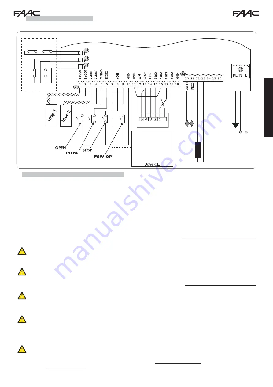
11.4.1 TERMINAL BOARD J1 - ACCESSORIES (FIG. 28)
J6=FCC - FCO - Manoeuvre stop command.
J5=RCL - Start of closing deceleration.
J3=ROP - Start of opening deceleration.
LOOP 1 - LOOP 1 magnetic loop (OPEN - terminals 1-2):
for OPENING.
LOOP 2 - LOOP 2 magnetic loop (SAFETY/CLOSE - terminals 3-4):
for SAFETY/CLOSING.
EF - Electrical stopping brake for motor locking.
OPEN - “Open” command (N.O. - terminal 5):
means any pulse generator (e.g.: button) which, by closing a contact, commands
opening and/or closing of the gate.
CLOSE - “Close” command (N.O. - terminal 6):
means any pulse generator (e.g.: button) which, by closing a contact, commands
closing of the gate.
FSW CL - Safety contact when closing (N.C. - terminal 7):
he purpose of the closing safety devices when closing is to protect the
area affected by the movement of the gate during the closing phase, reversing the motion. They never trip during the opening cycle.
The
CLOSING SAFETY DEVICES
, if tripped when the automated system is open, will prevent the closing movement.
If CLOSING safety devices are not connected, jumper terminals FSW CL and GND (Fig. 32).
NOTE: If this connection is made, it will not be possible to use the FAILSAFE control.
STOP - STOP contact (N.C. - terminal 8):
means any device (e.g.: button) which, by opening a contact, can stop movement of the
automated system.
If STOP devices are not connected, jumper terminals STOP and GND (Fig. 32).
FSW OP - Safety contact when closing (N.C. - terminal 9):
the purpose of the opening safety devices when opening is to protect
the area affected by the movement of the gate during the opening phase, reversing its motion. They never trip during the closing cycle.
The
OPENING SAFETY DEVICES
, if tripped when the automated system is closed, will prevent the opening movement.
If OPENING safety devices are not connected, jumper terminals FSW OP and GND (Fig. 32).
GND (terminals 10-11-19) - Accessories power supply negative
24 VDC (terminals 12-13) - Accessories power supply positive
The max. load of the accessories is 500 mA. To calculate absorption, refer to the instructions included with the
individual accessories.
OUT 1 - DECELERATION COMMAND (terminal 14):
signal telling the inverter that deceleration has begun.
OUT 2 - CLOSE COMMAND (terminal 15):
signal telling the inverter that the gate is closing.
OUT 3 - OPEN COMMAND (terminal 16):
signal telling the inverter that the gate is opening.
To avoid compromising correct system operation, do not exceed the power indicated in fig. 28.
OUT 4 - Output 4 open-col24 VDC (terminal 18): t
he output can be set in one of the functions described in Advanced Pro-
gramming Level (par. 11.5.2.). The default value for ALL PRE-SETTINGS is
BUS COMMUNICATION
.
Maximum load:
24 VDC with 100 mA.
60 W max
230 V~
230 V
~
50/60 Hz
11.4 ELECTRICAL CONNECTIONS


