11
FSW-CL FSW-OPEN
Fig. 3
ENGLISH
This operation changes the value of the parameters
So
and
SC
in Basic configuration and
FO
,
FC
,
oc
in Advanced configuration, setting them on the default
values as shown in the tables in paragraph 6.3.
Unlike the other parameters, the value of step
dF
is
not stored, thus allowing access to the menu through a
neutral condition, which is the one displayed every time the
configuration menu is opened..
If you do not wish to load any set of pre-defined parameters, leave
parameter
St
on
00
and press “F” to go on to the next parameter
Setting a set of pre-defined parameters that does not
correspond to the actual configuration of the barrier could
cause irreversible damage to the automated system, in
particular if the default corresponds to a beam length
shorter than the actual one.
5.3 BUS accessories menu
The E680 board is designed to connect up to 8 pairs of BUS
photocells. For the bus devices connected to the E680 board to be
detected and managed by it, they must be stored on the board. To
do this, proceed as follows:
•
cut off power from the board.
•
install and program the accessories using the desired address,
depending on the function you wish to use (as described in
paragraph 4.1.2)
•
power up the board.
•
access Basic Configuration, as described in paragraph 5.1
•
once programming step
bu
is reached,
no
, will be displayed,
indicating that here are no stored bus devices.
•
to perform entry, simultaneously press and hold the + and -
buttons for at least 5 seconds (during this time, the writing
no
will flash)
•
once the procedure is completed,
Y
will appear as confirmation.
•
when + and - are released, the display will show the current status
of the BUS devices, or
no
again, if there are no connected
BUS devices.
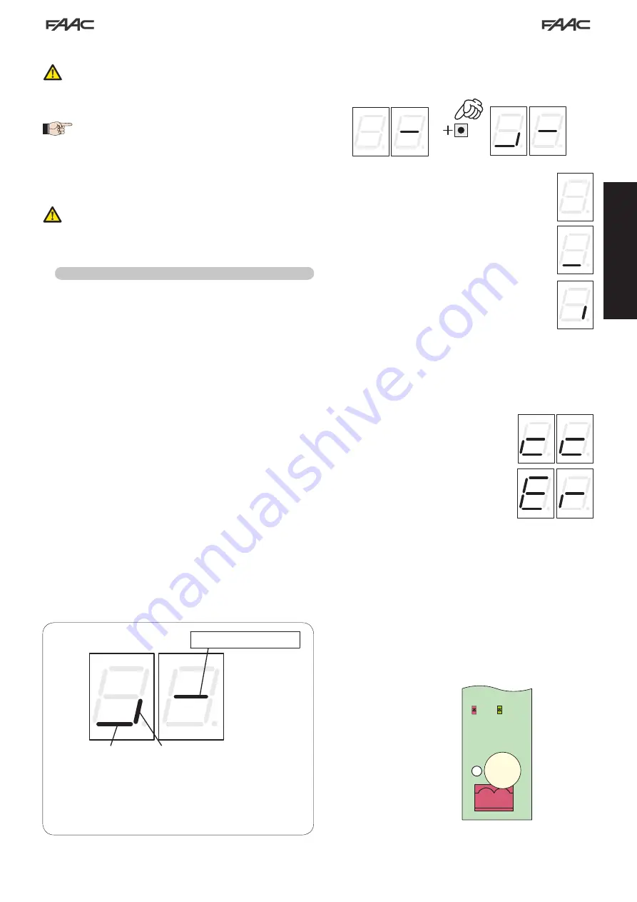
The following image (Fig. 3) shows the correspondence of the various
display segments to the different types of BUS devices that can be
connected to the system:
FSW CL:
BUS photocells placed to protect the gate
closing area
OPEN:
BUS photocells used as OPEN pulse generators
From the display of the status of the BUS devices, pressing the + key
enables the types of BUS devices present to be verified.
For example, the following photograph shows safety devices present
during closing and a pair of photocells functioning as open pulse:
For the automated system to operate correctly, the status
of the segments of the left-hand digit must correspond
to the automated system at rest and without pulse
generators or or safeties engaged.
When the CLOSE photocells are engaged, the bottom
segments will go on, as shown in the image to the side.
If the pair of OPEN pulse generator photocells is
engaged, the display will show the configuration of
segments shown in the image on the side of the page,
in which the corresponding vertical segment is on, and
will remain like this until the photocells are disengaged.
If involved, the pair of OPEN pulse generator photocells
commands opening of the automated system and
prevents it from closing until it is disengaged, like a
normal OPEN pulse received through terminal board
J1 (terminal 3).
The BUS communication system uses a self-diagnostic function able
to provide connection error signals or BUS accessories configuration
error signal.
The display will show a flashing
cc
if there is a
short circuit along the BUS line, as shown in the
figure. To solve the problem it is necessary to
carefully verify all the connections made.
The display will show a flashing
Er
as shown
in the image on the side of the page, should
more than one pair of photocells have the
same adress and in case of a calling or failsafe
error. Ensure that the settings are correct, with
reference to the indications given in paragraph
4.1.2
The status of the BUS and related input signals can also be seen by
analysing the two LEDs DL1 (red) and DL2 (green), which make it
possible to immediately verify if BUS communication is active or if
there is an error, and if there are any active inputs or not. The status
of the LEDs can be verified in the following tables:
J6
DL1 DL2
2Easy BUS
2
1
Bus status (always on)
Содержание B680H
Страница 1: ...B680H ...
Страница 2: ......
Страница 4: ......
Страница 150: ...26 a b DX SX a b c Fig 10 Fig 11 M M L1 L2 L3 L1 L2 L3 Fig 12 d Fig 13 Fig 14 Fig 15 a b Fig 16 ...
Страница 151: ...27 a b c d e f g h Fig 17 L ...
Страница 152: ...28 Fig 18 a b a b d Fig 19 c 1 2 Fig 20 ...
Страница 153: ...29 a b Fig 21 d e f c ...
Страница 156: ...32 Fig 31 a b c d e ...
Страница 157: ...33 Fig 32 f g ...
Страница 158: ......
Страница 163: ...5 1 2 Fig 18 ...
Страница 164: ......
Страница 165: ......


