16
ENGLISH
ENGLISH
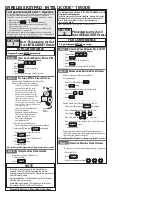
3.4. POSITIONING TRAVEL LIMIT PLATES
The 748 operator is equipped with an electro-mechanical travel
limit switch with roller, which, when a profiled plate secured at the
top of the rack activates its lever, commands the gate movement
to slow down and stop. Procedure for correct positioning of the
two travel limit plates supplied:
1) Power up the system.
2) Manually take the gate to opening position, leaving a space
of 2 cm from the mechanical travel limit stop position.
3) Slide the plate along the rack in opening direction and check
if the switch is activated before the end of the profiled part
(the FCA LED on the 748D equipment goes OFF).
4) Allow the plate to advance further until the switch wheel is
about 2-3 cm from the end of the plate’s straight area and
secure it provisionally.
5) Manually take the gate to closing position, leaving a space of
2 cm from the mechanical stop.
6) Slide the plate along the rack in closing direction and check if
the switch is activated before the end of the profiled part (the
FCC LED on the 748D equipment goes OFF).
7) Allow the plate to advance further until the switch wheel is
about 2-3 cm from the end of the plate’s straight area and
secure it provisionally.
8) When the slow-down and/or braking time (see instructions for
the 748D equipment) has been programmed, it may be
necessary to slightly correct the position of the plates, if the
stop points are not as required. If this operation is performed,
you must make sure that the gate never stops less than 2 cm
from the mechanical travel limit stops and that the electro-
mechanical travel limit wheel is at least 2 cm from the end of
the plate’s straight area; if necessary, adjust the slowing down
time and/or straighten the final profiled part of the plate (see
fig.12).
9) Re-lock the system. Important: before sending an opening or
closing pulse, make sure that the gate cannot be moved
manually.
10) Command a few complete cycles of the automated system,
checking that the gate never reaches the mechanical travel
limit stops.
3.5. MANUAL OPERATION
Should the need arise to operate the gate manually because of
a power failure or malfunction, release it by means of the releasing
device.
Proceed as follows:
• open the lid of the lock and insert the relative key in the lock
(fig. 13);
• turn the key clockwise and open the cover of the releasing
device as shown in figure 13.
To re-lock the system, return the cover of the releasing device to
its initial position.
Important: before giving a signal, ensure that the gate cannot
be moved manually.
N.B.: re-lock always the operator with gate in closed position.
4. START-UP
1) When you have carried out all the electrical connections,
locked the operator, and checked that it cannot be moved
by hand, power up the system.
2)Program the 748D equipment. Check the status of the
equipment’s inputs and verify if all safety devices are correctly
connected (the relevant LEDs must be lighted).
3) Run a few complete cycles to check if the automated system
and the accessories connected to it are operating correctly,
giving special attention to safety devices and to the
adjustment of the operator’s thrust force.
4) Hand over the User’s Guide to the customer, and describe how
the system works, as well as the operator release and locking
operations indicated in the said guide.
Fig. 12
Fig. 13