www.gatexpertstore.com
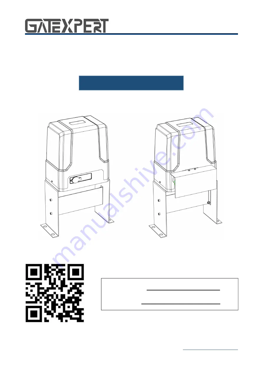
Sliding Gate Opener
User Manual
SL500DCL/SL800DCL
Website: www.gatexpertstore.com
E-mail: [email protected]
www.gatexpertstore.com
Sliding Gate Opener
User Manual
SL500DCL/SL800DCL
Website: www.gatexpertstore.com
E-mail: [email protected]