Operating Manual
46
8.1.1.5.4 Battery undervoltage alarm {1226} {1334}
If the undervoltage threshold is reached, this activates the contact. In contrast to the
acoustic alarm that is deactivated after a set time, this signal remains active as long
as the battery voltage is below the threshold. If the undervoltage fault cuts in, this
condition remains active as does the contact.
8.1.1.5.5 Battery overvoltage {1227} {1335}
Activates the contact in the event of battery overvoltage.
8.1.1.5.6 Inverter or smart boost overload {1228} {1336}
Activates the contact in the event of an error due to excessive power in the inverter or
the Smart Boost function. In the event that the inverter disconnects due to excess
power and it is attempting to restart, the contact is not activated until the end of the
attempts.
8.1.1.5.7 Overtemperature {1229} {1337}
Activates the contact in the event of overtemperature in the electronics or the
transformer.
8.1.1.5.8 No overtemperature alarm {1520} {1521}
Activates the auxiliary contact if no overtemperature alarm is active.
8.1.1.5.9 Active charger {1231} {1339}
Activates the auxiliary contact if the charger function is active. When the Smart-Boost
function is operating, the condition for activating the contact is not fulfilled.
8.1.1.5.10 Active inverter {1232} {1340}
Activates the auxiliary contact if the inverter function is active.
8.1.1.5.11 Smart-Boost active {1233} {1341}
Activates the auxiliary contact if the Smart-Boost function is active. For more
information on the smart boost function, refer to the manual for the IUPS101
inverter/charger.
8.1.1.5.12 AC In present with fault {1234} {1342}
Activates the auxiliary contact if there is voltage present at the AC In input but this
voltage does not fulfil the conditions for activating the transfer relay.
8.1.1.5.13 AC In present {1235} {1343}
Activates the auxiliary contact if a voltage is present at the AC In input. This condition
is independent of the state of the transfer relay.
8.1.1.5.14 Transfer relay drawn {1236} {1344}
Activates the auxiliary contact if the transfer relay is drawn.
Содержание iUPS101
Страница 1: ...Installation Operating Manual iUPS101...
Страница 55: ...Operating Manual 55...
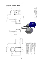
Страница 59: ...Operating Manual 59 11 5System Assembly Details...
Страница 62: ...Operating Manual 62 14 Certification 14 1Atex Label...
Страница 63: ...Operating Manual 63 14 2Atex Certificate...
Страница 64: ...Operating Manual 64...
Страница 65: ...Operating Manual 65...
Страница 66: ...Operating Manual 66...
Страница 67: ...Operating Manual 67...
Страница 68: ...Operating Manual 68 14 3iUPS101 EC Declaration of Conformity...
Страница 69: ...Operating Manual 69 14 4UPS System EC Declaration of Conformity...


