


Operating Manual
22
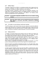
IMPORTANT!
For systems with periods of inactivity, such as a long shutdown
or moving/storing a mobile system where the UPS is not in use
and there is no AC mains supply. Users should remove the
incoming AC and DC supplies to the system when not in use.
WARNING!
If the batteries are to be disconnected in a hazardous area, then
an appropriately certified means of isolation must be provided.
WARNING!
All parts of the enclosure must never be opened while energised,
or when an explosive gas atmosphere is present.
4.2.10 iUPS101 protection
The IUPS101 is protected electronically against overloads, short-circuit, overheating
and reverse current (cabling of a voltage source on AC out).
In the event of overload or short-circuit at the output, the inverter stops for some
seconds and restarts. If the inverter is repeatedly encountering this situation in a
short period, it will stop permanently and will only start again via an operator’s
manual control.
If the battery voltage exceeds the programmed value the inverter stops and starts up
again when the voltage is less than the set level. If the iUPS101 is repeatedly
encountering this situation in a short period, it will stop permanently and will only start
up again via an operator’s control.
Important:
Overheating of the UPS due to operation in increased ambient
temperature or rated loads above those specified for your product may
lead to overheating of certain internal components of the unit. In this
case, the device will automatically limit its power output as long as this
abnormal situation persists.
The IUPS101 is protected from reverse polarity by means of a fuse
installed within the Ex ‘d’ enclosure.
4.2.11 Auxiliary contacts
The iUPS101 has two dry reversing contacts that are potential-free. The status of the
contacts in idle mode (deactivated) is indicated by the annotations, N.C. = normally closed
and N.O. = normally open.
Maximum contact loads: 230 Vac / 24 Vdc: 16 A or: max. 50Vdc/ 3A
These dry contacts are programmed by default for the following functions:
Contact no. 1 (AUX 1): The contact has a function of automatic start of generator (two wires).
The contact will be activated when the battery voltage is below a set value, during a given
time. The contact will be deactivated when the charge cycle as reached floating, or when the
Aux. 1 deactivation voltage is reached.
Contact no. 2 (AUX2): Alarm contact by default. It is deactivated when the inverter is out of
service or is working at reduced performance, either because of manual control or if there is
an operational fault such as overload, under-voltage of the battery, over-temperature, etc.
The functions of the two auxiliary contracts can be modified and programmed variously –
contact Extronics for details
Содержание iUPS101
Страница 1: ...Installation Operating Manual iUPS101...
Страница 55: ...Operating Manual 55...
Страница 59: ...Operating Manual 59 11 5System Assembly Details...
Страница 62: ...Operating Manual 62 14 Certification 14 1Atex Label...
Страница 63: ...Operating Manual 63 14 2Atex Certificate...
Страница 64: ...Operating Manual 64...
Страница 65: ...Operating Manual 65...
Страница 66: ...Operating Manual 66...
Страница 67: ...Operating Manual 67...
Страница 68: ...Operating Manual 68 14 3iUPS101 EC Declaration of Conformity...
Страница 69: ...Operating Manual 69 14 4UPS System EC Declaration of Conformity...


