


6 Use the agentStpMstVlanRowStatusAssociate object in the agentStpMstVlanTable to associate MST
instance 10 to VLAN 10 and MST instance 20 to VLAN 20.
•
For MST ID 20, the OID to set is 1.3.6.1.4.1.4413.1.1.1.2.15.14.1.1.10.10 (the final .10 is the VLAN ID)
•
For MST ID 20, the OID to set is 1.3.6.1.4.1.4413.1.1.1.2.15.14.1.1.20.20
Set the value to CreateAndGo (4).
7 Use the agentStpPortState in agentStpPortTable under agentStpSwitchConfigGroup to enable STP
on interface 1/0/1 and interface 1/0/2.
For instance 1 and 2, set the value to enable (1).
8 Use the agentStpMstPortPriority object in agentStpMstPortTable to change the port priority on
interface 1/0/2 to force the port to be the root port on the non-root bridge.
Configuring VLAN Routing
This section provides an example of how to configure 200 Series software to support VLAN routing.
The configuration of the VLAN router port is similar to that of a physical port. The main difference is
that, after the VLAN has been created, you must use the
show ip vlan
command to determine the
VLAN’s interface ID so that you can use it in the router configuration commands.
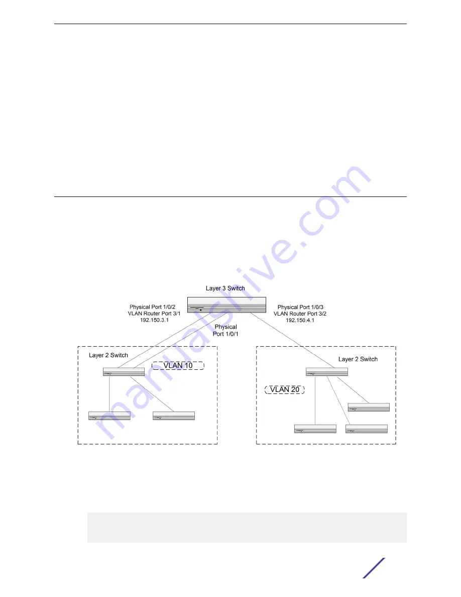
shows a Layer 3 switch configured for port routing. It connects two VLANs, with two ports
participating in one VLAN, and one port in the other. The script shows the commands you would use to
configure 200 Series software to provide the VLAN routing support shown in the diagram.
Figure 7: VLAN Routing Example Network Diagram
Using the CLI to Configure VLAN Routing
1 Create VLAN 10 and VLAN 20.
(Extreme 220) (Routing) #vlan database
vlan 10
vlan 20
exit
Configuration Examples
ExtremeSwitching 200 Series: Administration Guide
338


