Machine control
– Operating elements
Overview of control sections
10
099-0M37XM-EW501
16.07.2018
4.1.2
Control section B
Figure 4-3
Item Symbol
Description
0
1
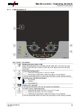
Display left / Lock function push-button
Switching the device display between various welding parameters. Signal lamps show
the selected parameter.
-------- Press for 3 s to put the machine into lock function
> see 4.3.5 chapter
.
2
Wire feed speed unit signal light
m/min --- Parameter value is displayed in meters per minute.
ipm ------ Parameter value is displayed in inches per minute.
Switching between metric or imperial system via special parameters
"P29"
> see 5.4 chapter
.
3
Material thickness signal light
Indication of the selected material thickness.
4
Welding current signal light
Display of the welding current in amperes.
5
Signal light, Wire speed
Lights when the wire speed is shown on the display.
6
Lock function signal light
Use display left / lock function push-button to switch on and off.
7
Correction voltage arc length signal light
Display of correction voltage arc length in volts.
8
Display, right
> see 4.2 chapter
V --------- welding voltage
9
Excess temperature signal light / Welding torch cooling failure
For error messages
> see 6 chapter
10
Coolant fault signal light
Indicates flow fault or low coolant level.
11
Second signal light
The displayed value is displayed in seconds.


