Machine control
– Operating elements
Welding data display
099-0M37XM-EW501
16.07.2018
11
Item Symbol
Description
0
12
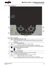
JOB number display (welding task)
> see 5.2.1 chapter
13
Status display signal light (Hold)
Display of mean values across the entire welding process.
14
Percent signal light
The displayed value is displayed in percent.
15
Material thickness unit signal light
mm ------- Parameter value is displayed in millimeters.
inch ------ Parameter value is displayed in inches.
Switching between metric or imperial system via special parameters
"P29"
> see 5.4 chapter
.
16
Display, left
Welding current, material thickness, wire speed, hold values
4.2
Welding data display
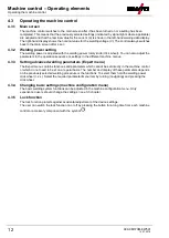
To the left of the parameter displays, there is the parameter selection push-button. It is used to select the
welding parameters to be displayed and their values.
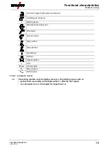
Each time one the button is clicked, the display proceeds to the next parameter (signal lights indicate the
selection). After reaching the last parameter, the system is restarted with the first one.
Figure 4-4
MIG/MAG
Parameter
Nominal values
[1]
Actual values
[2]
Hold values
[3]
Welding current
Material thickness
Wire feed speed
Welding voltage
MMA
Parameter
Nominal values
[1]
Actual values
[2]
Hold values
[3]
Welding current
Welding voltage
When settings are changed (e.g. wire feed speed) the display immediately switches to the nominal value
setting.
[1]
Nominal values (before welding)
[2]
Actual values (during welding)
[3]
Hold values (after welding, display of mean values for entire welding process)


