


Upgrading The Computer
Upgrading the Hard Disk Drive 6 - 5
6
For
Model A
computers
(see overleaf for Model B)
:
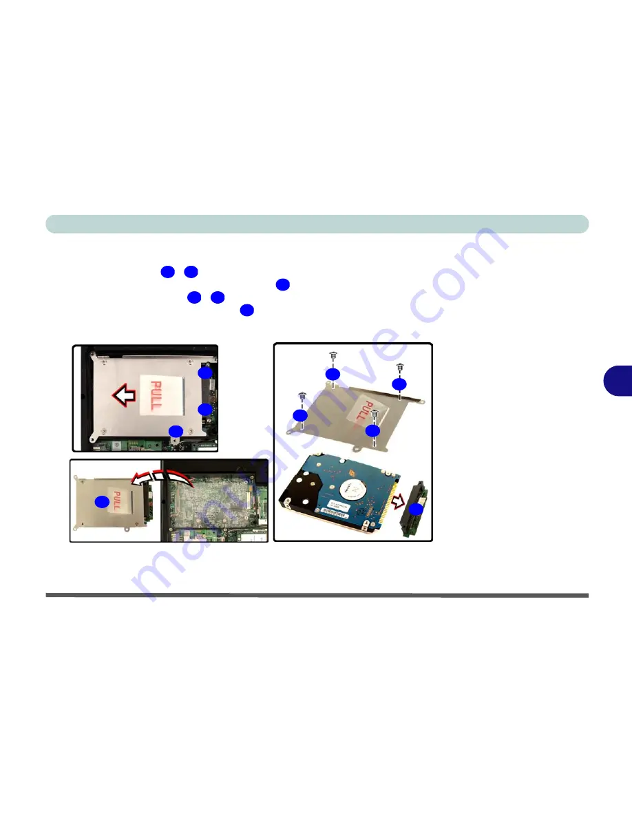
3.
Remove screws
-
from the hard disk assembly.
4.
Pull the tab upward and lift the assembly
out of the computer.
5.
Remove the
4
screws
-
to release the hard disk from the assembly
cover, and remove the connector
.
6.
Reverse the process to install any new hard disk.
12
14
Figure 6 - 3
HDD & Cover
Assembly
Removal
(Model A
Computers Only)
15
16
19
20
12
13
14
15
16
17
18
19
20
Содержание Notebook
Страница 1: ......
Страница 2: ......
Страница 20: ...XVIII Preface ...
Страница 56: ...Features Components 2 14 2 ...
Страница 80: ...Drivers Utilities 4 12 4 ...
Страница 96: ...BIOS Utilities 5 16 5 ...
Страница 115: ...Modules Options Bluetooth Module 7 7 7 Figure 7 4 Bluetooth Audio Setup Windows XP Click to make volume controls appear ...
Страница 119: ...Modules Options PC Camera Module 7 11 7 Figure 7 5 PC Camera Audio Setup Windows XP ...
Страница 136: ...Troubleshooting 8 12 8 ...


