


11
2527245-02-01/22 (translation of the original operating instructions)
Operating Instructions
Safety System MGBS-P-L.-AP…
EN
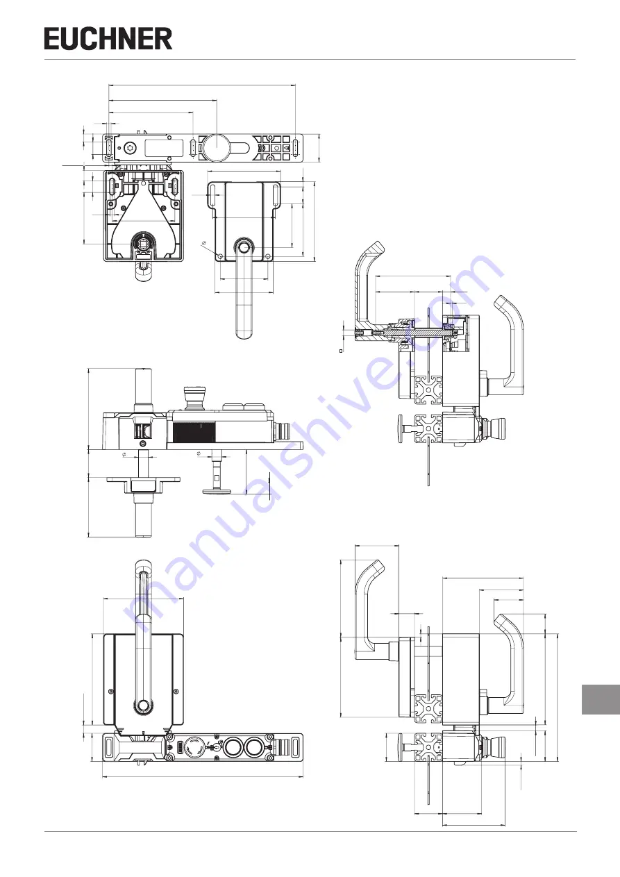
7.4.
Dimension drawing (example illustration)
11
18
6,2
120
266
40
min. 3,5
max. 4,15
14,8
16,5
6,3
89,4
73,7
154
115,5
40
84,5
14
14
34 / 64 / 84
min. 11,5 max. 16,5
40
130
114
286
42
63
115,5
40
56
90
min.
1
max.
6
44
min.
7,5
max.
12,5
130
182
40
110,6
5
29
22,2
62,3
114,2
7,5
24
89,4
6,4
114
68
75
6,4
104,4
83
62,5
107
8
55,5
11,5
2,4
40
~
5
Square drive
Profile