


3
GENERAL
Table Of Contents
Figure 1. Etnyre RTN ........................................................ 4
Figure 2. Unit Nameplate or Certification Label ................ 5
Figure 3. Unit Nameplate and Decals ............................... 6
Figure 4. Standard Hardware ............................................ 8
Figure 5. Inspection of Kingpin for wear ........................... 9
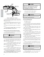
Figure 6. Identification of Controls .................................. 10
Figure 7. Compression Block Positions .......................... 11
Figure 8. Gooseneck to Platform Connections ............... 11
Figure 9. Ride Height Adjustment ................................... 12
Figure 10. Extension Brackets ........................................ 13
Figure 11. Blocking Under Rear of Trailer ....................... 14
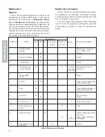
Figure 12. Maintenance Checkpoints ............................. 19
Figure 13. Check Oil Level of Oil Lubricated Bearings. .. 21
Figure 14. Tightening Sequence ..................................... 21
Figure 15. Eccentric Bolt Inspection .............................. 22
Figure 16. Root Weld Gap ............................................. 23
Figure 17. Multiple Pass Recommended Method ........... 23
Figure 18. No Weld Zones .............................................. 24
Figure 19. Alignment of Axle ........................................... 24
Figure 20. Height Control Valve Asm .............................. 25
Figure 21. Proper Tire Inflation ....................................... 26
Figure 22. Removal of Tires and Hub Piloted Wheels .... 27
Figure 23. Checking Oil Level in Hub ............................. 28
Figure 24. Brake Air Supply System - 2 Axle Shown ...... 29
Figure 25. Relay Emergency Valve ................................. 30
Figure 26. Brake Chamber .............................................. 31
Figure 27. Brake Components ........................................ 32
Figure 28. Slack Adjuster Lubrication Points .................. 33
Figure 29. Measuring Maximum Stroke .......................... 33
Figure 30. Gooseneck Socket Connection .................... 39
Figure 31. Hydraulic Oil Check ....................................... 40
Figure 32. Directional Control Valve Pressure Relief ...... 40


