background image

23

MAINTENANCE

Welding Guidelines

The following precautions and recommendations

must be read and understood by qualified personnel
prior to weld installation of Ridewell Air-Ride Trailer
Suspensions to trailer axles. Any welding procedures
or materials that do not clearly fall within these guide-
lines could compromise the integrity and safety of the
installation.

Welding Methods, Materials & Personnel

A)  All welders and welding operators should be

certified per A.W.S (American Welding Society) D1.1
Section 5 Procedures or equal.

B)  Recommended welding methods are shielded

metal arc (stick), gas metal arc (solid wire) or flux cored
arc (tubular wire) welding. Whatever electrode and
method used must develop a minimum weld tensile
strength of 70,000 P.S.I. Refer to the electrode
manufacturer's recommendation for voltage, current and
shielding medium for the diameter electrode to be used
so the best fusion and mechanical properties can be ob-
tained.

C)  All electrodes used should meet A.W.S. Section

5 Specifications and Classifications for welding car-
bon and low alloy steels.

D)  If shielded metal arc electrodes (stick) are used,

they must be new and unused, dry, free of contami-
nants and come from a stock that has been purchased
and stored per A.W.S. Section 4.5.2., Low Hydrogen
Electrode Storage Specifications.

Weld Joint Preparation

A)  All grease, dirt, paint, slag or other contami-

nants must be removed from the weld joint without
gouging the axle tube.

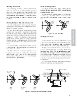
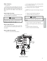
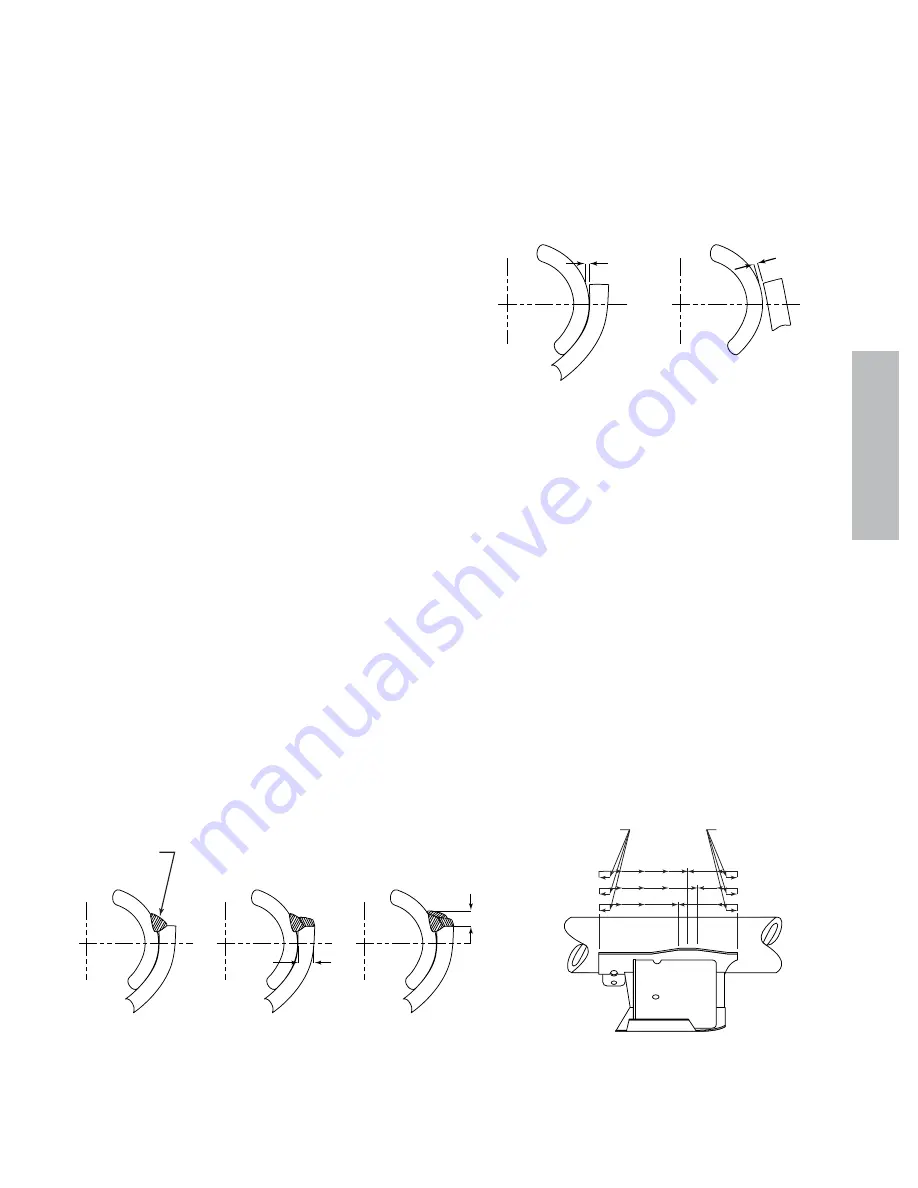
B)  Insure the lower beam assembly fits the axle with

a weld root gap of 1/16" to 1/8" maximum between the
welding wings or uprights as illustrated. (See Figure
16.)

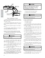
Figure 16.  Root Weld Gap

Welding Procedure

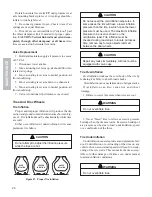
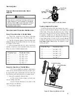
A)  Ground the axle to one of the attached axle parts

such as the air chamber brackets, cam brackets, or the
brake spider. Never ground the axle to a wheel or
hub as the spindle bearing may sustain damage.

B)  The axle assembly should be at a minimum tem-

perature of 60º F (15º C) prior to welding. Pre-heating
the weld zone to the axle manufacturer's recom
-
mended pre-heat temperature is recommended. This
will minimize the formation of martensitic or brittle
metal structures in the fusion line or the heat affected
zone which may contribute to a premature fatigue fail-
ure in service.

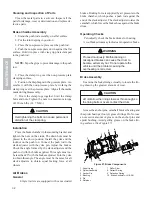
C)  The joint to be welded should be positioned in

the flat or horizontal position if possible.

1/16 to
1/8 Max

1/16 to
1/8 Max

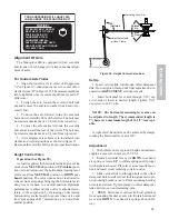
FIRST
PASS

SECOND
PASS

THIRD
PASS

1/2

3/8 FILLET
WELD

1/2

THIRD PASS

ARC START

ARC START

SECOND PASS

FIRST PASS

THIRD PASS
SECOND PASS
FIRST PASS

Figure 17.  Multiple Pass Recommended Method

Содержание BLACKHAWK RTN Series

Страница 1: ...BLACKHAWK TRAILERS Limited Series Paver Special Classic Series Custom Series MO RTN 05 Serial Number Q27423 and Up Supercedes manual number MO RTN 02 ...

Страница 2: ... compromise your products service life and safety Under torque and over torque can cause thread and or nut damage and may result in the loss of a wheel Recheck torque after the first 50 to 100 miles of service Parts may seat natu rally causing the torque to drop Proper torque is essential for the service life and safety of this product DANGER Recommended Torque Dry 450 500 ft lbs NOTE All threads ...

Страница 3: ......

Страница 4: ......

Страница 5: ...irs or alterations have been made or for components not manu factured by the Company except to the extent of the warranty given by the original Manufacturer This warranty does not apply to 1 Normal start up services normal maintenance services or adjustments usually performed by the selling dealer factory service representative or customer personnel 2 Any product manufactured by Etnyre Trailer Co ...

Страница 6: ...s 24 Alignment Of Axle For Tandem Axle Trailer 25 Height Control Valve 25 Set Up 25 Adjustment 25 Valve Replacement 26 Tires And Disc Wheels 26 Tire Inflation 26 Tire Overinflation 26 Tire Underinflation 26 Matching Dual Tires 27 Removing Tire and Disc Wheel Assembly 27 Mounting and Demounting Tires on Disc Wheels 27 Mounting Tire and Hub Piloted Type Disc Wheels 27 Checking Tightness on Mounted D...

Страница 7: ...ngs 21 Figure 14 Tightening Sequence 21 Figure 15 Eccentric Bolt Inspection 22 Figure 16 Root Weld Gap 23 Figure 17 Multiple Pass Recommended Method 23 Figure 18 No Weld Zones 24 Figure 19 Alignment of Axle 24 Figure 20 Height Control Valve Asm 25 Figure 21 Proper Tire Inflation 26 Figure 22 Removal of Tires and Hub Piloted Wheels 27 Figure 23 Checking Oil Level in Hub 28 Figure 24 Brake Air Suppl...

Страница 8: ...424 9393 or 366 0123 in Washington D C area or write to NHTSA U S Department of Transportation Washington D C 20696 You can also obtain other information about motor vehicle safety from the hotline GENERAL This manual contains operation maintenance and service instructions for the Etnyre RTN Series trailers see figure 1 The operating instructions must be read and understood before operating the un...

Страница 9: ...GVWR or GAWR at the specified speed These weight limitations are independent of road weight limitations imposed by law Tire and Rim Data The certification label lists the correct rim size tire size and tire inflation pressures for the trailer WARNING Do not use undersize rims or tires Do not underin flate or overinflate the tires System Specifications Unit specifications are listed in the General ...

Страница 10: ...t 4 Q513124 1 Decal Lift Arm Release Pos 5 Q513123 1 Decal Lift Arm Storage Pos 6 Q512962 1 Decal Bird RH Q513296 1 Decal Bird LH 7 Q512963 2 Decal Word Blackhawk 8 Q509853 1 Decal Deck Height 3 Pos 9 Q513970 1 Decal Gooseneck Air Lock Control 10 Q471243 2 Decal Warning Sideload 11 2790527 60 Tape Conspicuity 2 In Red White 12 Q451436 1 Decal Return 13 Q451435 1 Decal Pressure 14 Q401734 1 Decal A...

Страница 11: ...th close coupled 4th axle PRTN55TD3 T1 Load Capacity 55 tons in any 12 0 of deck in 3 1 14 1 spread axle configuration High lift gooseneck 35 travel Pin and stirrup design Pin setting 16 Swing clearance 84 Fifth wheel height 50 adjustable 2 no blocks Vertical gooseneck locking pin air operated Frame reinforced For 4th axle Main frame 4 beam 16 fully cambered Deck height 22 adjustable no blocks Gro...

Страница 12: ...NF 19 14 26 20 27 20 37 28 3 8 16 UNC 31 23 42 31 44 33 59 44 24 UNF 35 26 47 36 49 37 67 50 7 16 14 UNC 49 37 67 50 70 52 95 71 20 UNF 55 41 75 56 78 58 105 79 1 2 13 UNC 75 57 100 77 105 80 145 110 20 UNF 85 64 115 86 120 90 165 120 9 16 12 UNC 110 82 145 110 155 115 210 155 18 UNF 120 91 165 125 170 130 230 175 5 8 11 UNC 150 115 205 155 210 160 285 215 18 UNF 170 130 230 175 240 180 325 245 3 ...

Страница 13: ...r measures less than 1 7 8 at any point see figure 5 3 Check the bolts for tightness Tighten if required Refer to Table 1 for correct torque values 4 Connect the trailer to the fifth wheel 5 Connect the glad hands and build up reservoir air pressure Make sure that air line connections between trailer and truck are made 6 Connect the plug into the electrical socket Make sure that electrical connect...

Страница 14: ...oint where the frame contacts the ground 9 Power pack units shut off power pack engine Truck operated units disengage truck pump Figure 6 Identification of Controls 11 Move the platform height control to the Raise position until the compression blocks fall into the Transport position 12 Move the platform height control to the Lower position until the compression blocks are completely seated 13 Ins...

Страница 15: ...n fifth wheel height This adjustment is accom plished by positioning the compression blocks to mesh with the gooseneck link through a range of positions An adjustable stop cam is provided to stop the com pression blocks in a preselected position See figure 9 NOTE The top tooth of the compression block must always be above the top tooth of the gooseneck link when the block and link are engaged in t...

Страница 16: ...t raise loaded trailer so high as to lift the front axle off the ground Damage to the trailer frame and or suspension could occur WARNING Do not make turns with the trailer in the high lift position Damage to the trailer and or tractor could occur Compression Block Handle Compression Block Position for Minimum Fifth Wheel Height or Maximum Ride Height Compression Block Handle Compression Block Pos...

Страница 17: ...the trailer slowly Extension bracket will not support the full load weight 3 Center the load Do Not load to one side Position the load for proper weight distribution 4 Fasten the load to the trailer WARNING The load must be securely and adequately fastened to the trailer WARNING Keep hands and feet clear of the point where the frame contacts the ground WARNING Extension Brackets Maximum width not ...

Страница 18: ... off the trailer slowly Extension bracket will not support the full load weight 4 Center the load Do Not load to one side Position the load for proper weight distribution 5 Fasten the load to the trailer General Road Check Procedures During road stops check the trailer and the load us ing the following procedures 1 Check the fastening equipment WARNING The load must be securely and adequately fast...

Страница 19: ... Check the tire inflation Inspect the tires for cuts or other damage WARNING Do Not bleed air from the tires when they are hot 6 Inspect the lights turn signals and reflectors for operation WARNING Do Not operate a trailer needing repair Correct any problems found during the road check immediately ...

Страница 20: ... points Trailer may be adjusted using manual raising and lowering valve or 3 3 height control Air pressure gauges may be located on suspension air bag for developing air pressure for axle load charts Shimming objective is to have all rear section bottom beam flanges level top of axle to bottom flange of rear beam should be 6 1 2 at standard ride height A chart should be kept of all the loads that ...

Страница 21: ... C have more shims than Shim Point B and Shim Point B should not have more shims than Shim Point A Axle weights should be checked on a certified scale For backing empty trailer with stinger air bags deflated and shims removed Do not engage when traveling forward A 503 05 WARNING Remove the axle extension when traveling with an unloaded trailer If this is not practical all shims should be removed b...

Страница 22: ...basis of whichever occurs first The first column of Maintenance Table 2 should be used to locate the applicable maintenance procedure and illustration Figure 12 shows the maintenance points ITEM NO ITEM Day Wk Mo 25 000 mi 50 000 mi QUAN TYPE or REMARKS or 6 mo or 1 year 1 5th Wheel Plate X Multipurpose Grease No 1 Kingpin No 0 Below 32ºF X Inspect 2 Frame Decking X Check 3 Undercarriage X Check 4...

Страница 23: ...lic Oil Power Pack 16 with Hydraulic Filter X 1 Period Shown or 50 Power Element hours of Power Pack Pack Operation See Parts Manual 17 with Battery X Fill as Required Use Power Distilled Water Pack 18 with Engine X Check Air Cleaner Power and Motor Mount Bolts for Pack Tightness Check module isolators See Engine Manual for Additional Maintenance Information Table 2 Maintenance Schedule Figure 12 ...

Страница 24: ...d Failures are the result of metal fatigue caused by flexing and vibration They will appear as cracks in the steel frame members If repairs are needed Do Not operate the unit until the repairs are made Structural repairs must be done by persons experienced in this field NOTE Failure to maintain decking in good condi tion may cause damage to crossmembers Weld Repairs Minor repairs to crossmembers f...

Страница 25: ...e suspension is designed to dampen the shocks transmitted from road surface to trailer frame through the Air Springs The Height Control Valve is used to maintain the proper ride height from air spring to chassis whether empty or loaded by controlling the volume of air in the springs You may use either a single or dual leveling height control valve system on your trailer This service manual address...

Страница 26: ...r mounting height If measure ment is incorrect adjust height control valve until proper mounting height is achieved 8 Check all air connections for leaks and tighten if needed 9 Inspect air lines They should be free from sharp objects and secured to prevent premature failure 10 Eccentric bolt inspection See Figure 15 Figure 15 Eccentric Bolt Inspection Preventive Maintenance Daily Visually inspect...

Страница 27: ... nants and come from a stock that has been purchased and stored per A W S Section 4 5 2 Low Hydrogen Electrode Storage Specifications Weld Joint Preparation A All grease dirt paint slag or other contami nants must be removed from the weld joint without gouging the axle tube B Insure the lower beam assembly fits the axle with a weld root gap of 1 16 to 1 8 maximum between the welding wings or uprig...

Страница 28: ...e weld is cracked or broken the weld Figure 18 No Weld Zones can only be repaired if the crack or break does not extend into the axle tube To repair the weld grid or back gouge the weld crack down to the base metal If the crack extends into the axle tube or if any other area of the axle is cracked the axle must be replaced Apply the repair weld according to the information in Sec tions 1 3 of the ...

Страница 29: ...asing horizontal lever arm length to a point where valve and lever arm approach 45º maximum up or down from neutral position Figure 20 Height Control Valve Asm Set Up 1 Insert vertical link rod through offset dampener link Do not tighten clamp until final adjustment dis cussed in ADJUSTMENT section is made 2 Insert horizontal lever arm through 5 16 cap screw side of insert to desired length Tighte...

Страница 30: ...pressure while the tires are hot Figure 21 Proper Tire Inflation CAUTION Do not exceed the cold inflation pressures In some cases the rim will have a lower inflation pressure than the tire in which case the lower pressure must be used The maximum inflation pressure to be used is shown on the certification label Tire inflation must be checked during road stops to locate air losses Also remove any f...

Страница 31: ... approved procedures The following points must be considered when changing or repairing tires on disc wheels 1 Do not mix rim or wheel components They may come apart during inflation 2 Check the rim base side rings and lock rings for cracks or other damage Do not attempt to repair disc wheels Scrap damaged parts 3 Match the duals 4 Use only correct rim sizes 5 Keep rims clean and painted to avoid ...

Страница 32: ...ub over the spindle being careful to avoid damage to the spindle seal and brake 3 Put the outer cone into position 4 Tighten the inner spindle nut while rotating the hub both directions until a slight bind is felt 5 Loosen the nut 1 4 turn The hub must rotate freely 6 Install the inner nut lock and place the outer lock washer on the spindle 7 Tighten the outer nut 8 The end play must be 001 in 025...

Страница 33: ...ly the same pressure as is present in the tractor reservoir The relay emergency valve will keep the trailer brakes applied until the emergency line pres sure reaches 60 PSI 4 14 Bar The brakes will then be released 2 When the towing vehicle and the trailer are trav eling over the road the brakes are released and the emer gency line and reservoir are charged to full pressure 3 When the service brak...

Страница 34: ... PSI 6 2 6 9 Bar make and hold a full service brake application A two minute check must show a pressure drop of no more than 8 PSI 0 55 Bar for the combination vehicle system 7 If Step 6 indicates possible leakage apply soap suds on the relay emergency valve cover and exhaust port Aone inch 25 4 mm bubble in not less than three seconds is permissible Correct all leaks as indicated 8 Place the trac...

Страница 35: ...uts from the mounting studs Remove the air chamber Brake Chamber Disassembly 1 Clean the exterior of the brake chamber 2 Put a mark on the parts so they can be reassembled in the same relative positions 3 Pull out the push rod and clamp the push rod in the extended position with vise grip pliers NOTE Tape the grips to prevent damage to the push rod 4 Remove the bolts from the clamp ring 5 Spread t...

Страница 36: ...nd the push rod with the brakes applied This angle must not be less than 900 with the brakes adjusted Turn the yoke to obtain this angle The angle must be the same for all slack adjusters to obtain equal braking force at all wheels Air Brakes General Etnyre trailers are equipped with cam actuated brakes Braking force is supplied by air pressure in the brake chamber which pushes a push rod against ...

Страница 37: ... tect against dirt water salt and other corrosive elements Nevertheless periodic lubrication is recommended 1 Grease the automatic slack adjuster a The styles of grease plugs or reliefs may vary according to models b See Crewson Brunner service data for the approved types of lubricant 2 Test adjuster function Figure 28 Slack Adjuster Lubrication Points Testing Adjuster Function Check the operation...

Страница 38: ...clevis more than 1 16 remove the clevis and cut the rod to length A minimum of 1 2 thread engagement in the clevis body is required If this is not the case install a new pushrod and cut to length or use an extended length Crewson Brunner clevis 10 Tighten jam nut to a minimum of 50 ft lbs 11 Remove both clevis pins and template 12 Before installing auto slack adjuster coat the S cam spline both cl...

Страница 39: ...s during installation or at brake relining By constantly manually adjusting the hex shaft the internal clutch life can be shortened The proper way of checking an auto slack to see if it is working within specifications is to measure the working stroke CAUTION Check the brake adjustment frequently during the first 500 miles after relining Overloading or using only the trailer brakes to stop the com...

Страница 40: ...Restricted tubing or hose line Locate and remove restriction No air pressure due to a Broken line Locate leak and repair b Failure in tractor air supply Troubleshoot tractor air system Single brake dragging or locked Broken component within brakes Replace broken part a Retract spring b Cam roller c Shoe d Lining fasteners e Anchor pin f Spider Flat spot on cam roller or camshaft Replace defective ...

Страница 41: ...ing or hose Locate and remove restriction Defective relay emergency valve Clean and repair or replace valve Brakes release too slowly Brakes need adjustment or Adjust and lubricate brakes lubrication Brake components binding Align brackets or replace bent components Exhaust port or relay emergency Clean valve valve restricted or plugged All brakes do not release Brake air system improperly connect...

Страница 42: ... emergency valve leaking Repair or replace valve brakes released Leaking tubing or hose line Tighten or replace leaking lines Excessive leakage with Relay emergency valve leaking Repair or replace valve brakes applied Leaking brake chamber or Tighten clamp ring or replace diaphragm diaphragm Leaking tubing or hose line Tighten or replace leaking lines Excessive leakage with emergency Defective rel...

Страница 43: ...re is supplied by the tractor pump in wet line systems or by the optional hydraulic power pack mounted in the trailer frame Refer to the system description and repair procedures when checking or servicing hydraulic systems Hydraulic Power Pack Filter Use only Etnyre approved parts to ensure proper functioning First apply a film of oil to the gasket and hand turn the filter until the gasket contact...

Страница 44: ...he adjusting screw with a wrench while checking the relief pres sure The pressure shown on the gauge must read 2500 PSI plus or minus 50 PSI 172 Bar plus or minus 3 Bar If the pressure is not correct adjust the relief valve adjusting screw to obtain the correct relief pressure Turn the adjusting screw in a clockwise direction to increase the relief valve pressure Turn the adjusting screw in a coun...

Страница 45: ...ak on cylinder head Repack head External leak at fittings Remove and reseal or replace fittings Defective control valve Repair or replace valve Overload on trailer Do not exceed capacity of trailer Hydraulic oil cold Cycle oil to raise temperature and improve oil flow Excessive hydraulic system noise Air cavitating the system due to a Low oil level Fill system b Suction line leaks air foam Replace...

Страница 46: ...__________ Address ____________________________________________ City State Zip ____________________________________________ Phone ____________________________________________ Date Sent ____________________________________________ Manual Number upper right corner of front cover __________________________________________________________ Manual Title __________________________________________________...

Страница 47: ... compromise your products service life and safety Under torque and over torque can cause thread and or nut damage and may result in the loss of a wheel Recheck torque after the first 50 to 100 miles of service Parts may seat natu rally causing the torque to drop Proper torque is essential for the service life and safety of this product DANGER Recommended Torque Dry 450 500 ft lbs NOTE All threads ...

Отзывы: