


29
MAINTENANCE
5. Connect the emergency line. The brakes must re-
lease.
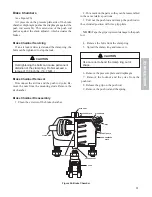
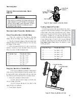
Air Reservoir
Drain condensation from the reservoir while the res-
ervoir is pressurized. Cables for the drain valves are
located on the roadside of the trailer frame. Listen for
leaks after releasing the drain valve cables.
Air Hoses and Tubing
Air hoses and tubing must be checked for chafing,
bends and kinking. Replace faulty parts.
Brake Relay Emergency Valve
The air system tests may disclose a malfunction of
the relay emergency valve. Repair or replace faulty
units. Contact an authorized representative of the origi-
nal equipment manufacturer for relay valve servicing.
Air Brake Chambers
The air system tests should disclose any malfunc-
tioning brake chambers. Repair or replace faulty units.
The diaphragm and any worn parts must be replaced
When replacing the diaphragm or the spring, replace
the corresponding parts for the other chamber on the
same axle to aid in even brake application and release.
Examine the yoke pin for wear and replace it if neces-
sary.
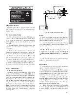
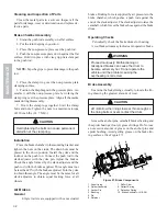
Brake Air Supply System Description
(see Figure 24)
The trailer relies on the tractor for its air supply. A
description of the system operation follows:
1. When the service and emergency lines are con-
nected to the towing vehicle, the reservoir is charged to
approximately the same pressure as is present in the
tractor reservoir. The relay emergency valve will keep
the trailer brakes applied until the emergency line pres-
sure reaches 60 PSI (4.14 Bar). The brakes will then be
released.
2. When the towing vehicle and the trailer are trav-
eling over the road, the brakes are released and the emer-
gency line and reservoir are charged to full pressure.
3. When the service brakes are applied in the towing
vehicle, the pressure is increased in the service line.
This fills the brake chambers with the same pressure as
the service line and applies the trailer brakes.
4. Releasing the service brakes will cause the pres-
sure in the service line to decrease, causing the relay
emergency valve to exhaust the pressure from the brake
chambers.
5. The trailer brakes can also be applied indepen-
dently from the tractor brakes by actuating a hand con-
troller. This supplies air pressure to the service line.
6. The brakes will also apply if the pressure in the
emergency line is reduced to about 30 PSI (2.07 Bar).
A gradual decrease in the emergency line pressure will
cause a gradual increase in the pressure to the brake
chambers.
7. A sudden release of pressure in the emergency line
Figure 24. Brake Air Supply System - 2 Axle Shown
EMERGENCY
SERVICE
BRAKE CHAMBER Ref. Typ
Air Reservoir
ECU/Valve Asm
ABS Relay Valve
Air Reservoir
1/2" Tubing
1/2" T
ubing
Hose Asm
Hose Asm
Hose Asm
Hose Asm
3/8" Tubing
3/8" T
ubing
3/8" Tubing
Emergency
Release Valve
Jumper
Hose
Jumper
Hose
5/8" Tubing
5/8" Tubing


