


31
MAINTENANCE
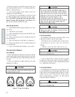
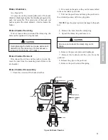
Brake Chambers
(see Figure 26)
Air pressure on the pressure plate side of the brake
chamber diaphragm pushes the diaphragm against the
push rod assembly. This extension of the push rod
pushes against the slack adjuster, which actuates the
brakes.
Brake Chamber Servicing
If an air leak is detected around the clamp ring, the
bolts can be tightened to stop the leak.
CAUTION
Overtightening the bolts can cause permanent
distortion of the clamp ring. Do Not exceed a
torque of 130 inch lbs. (14.7 N.M..)
Brake Chamber Removal
Disconnect the air line and the push rod yoke. Re-
move the nuts from the mounting studs. Remove the
air chamber.
Brake Chamber Disassembly
1. Clean the exterior of the brake chamber.
2. Put a mark on the parts so they can be reassembled
in the same relative positions.
3. Pull out the push rod and clamp the push rod in
the extended position with vise grip pliers.
NOTE: Tape the grips to prevent damage to the push
rod.
4. Remove the bolts from the clamp ring.
5. Spread the clamp ring and remove it.
CAUTION
Use care not to bend the clamp ring out of
shape.
6. Remove the pressure plate and diaphragm.
7. Remove the locknut and the yoke from the
push rod.
8. Release the grip on the push rod.
9. Remove the push rod and the spring.
Figure 26. Brake Chamber
INLET PORT
INLET
PRESSURE PLATE
DIAPHRAGM
PUSH ROD ASSY
YOKE
DRAIN HOLE
DRAIN HOLE
CLAMP RING
NON-PRESSURE
PLATE


