28
MAINTENANCE
25. If the inside tire and disc wheel assembly was not
removed, inflate the tire to the proper pressure.
Checking Tightness on Mounted Dual Disc
Wheels
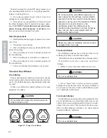
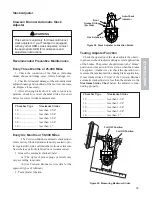
Check the flange nut, torque after the first 50-100
miles of service. Tighten the nuts as shown in Figure
14.
Hubs
Hub Removal
Demountable disc wheels must be removed before
removing hubs. Support the hub assembly prior to re-
moval. The hub and drum are removed as an assembly
using the following procedure.
1. Loosen the brake adjustment by turning the ad-
justing screw on the slack adjuster.
2. Remove the hub.
3. Bend the flap or tang of the lockwasher from the
flat of the outer spindle nut.
4. Remove the outer spindle nut, two (2) lockwash-
ers and the inner spindle nut.
5. Pull the hub and drum assembly carefully to avoid
damage to the bearing, spindle and inner seal. Catch
the bearing cones as the hub is removed from the
spindle.
Inspection and Cleaning
While the hub is removed, inspect the condition of
the brake drum and linings. Also check the condition
of the cups, cones, seal and axle ring.
Preparing Bearing for Assembly
Coat the bearing cones and cups with oil prior to
assembly.
Hub Installation
After the parts have been cleaned, inspected and
bearings oiled, install as follows:
1. Assemble the inner cone and seal into the hub.
2. Place the hub over the spindle, being careful to
avoid damage to the spindle, seal and brake.
3. Put the outer cone into position.
4. Tighten the inner spindle nut while rotating the
hub both directions until a slight bind is felt.
5. Loosen the nut 1/4 turn. The hub must rotate freely.
6. Install the inner nut lock and place the outer lock-
washer on the spindle.
7. Tighten the outer nut.
8. The end play must be .001 in. (.0254 mm) to .010
in. (.254 mm).
9. Lock the outer spindle nut in place by bending
the tangs or edge of the lockwasher over one flat on the
outer nut.
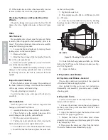
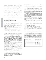
Figure 23. Checking Oil Level in Hub
10. Install the hub cap gasket and hub cap. Fill the
hub to the "Full" line on the hub cap window (see Fig-
ure 13 & Figure 23).
11. Adjust the brakes.
Air Systems and Brakes
Air Systems and Brakes - General
This section contains a description of the operation
of the trailer brake air supply system.
Also included in this section are test instructions,
disassembly and assembly procedures and a trouble-
shooting guide.
Air System Tests
A series of tests must be run daily before operating
trailers with air brakes.
1. Connect the air lines, turn on the air, and pressur-
ize the system. The system must hold 100 PSI (7 Bar)
pressure minimum.
2. Apply the brakes. Inspect the brake action on all
the wheels for proper application.
3. Release the brakes. The brakes must release
promptly. Air pressure must discharge quickly from the
relay emergency valve.
4. Disconnect the emergency line from the trailer.
The trailer brakes must automatically apply.
OIL LEVEL


