


25
MAINTENANCE
Alignment Of Axle
The Monopivot 240 is equipped with an eccentric
bolt in one or both hangers for simple, manual align-
ment of axles.
For Tandem Axle Trailer
1. Align the forward axle to center of kingpin (see
"A" in Figure 19), then align rear axle to center of for-
ward axle (see "B" in Figure 19). The measurement from
left to right side of axle centers should not exceed 1/8"
difference.
2. To align the axle, loosen the eccentric bolt lock
nut and remove the anti-turn washer from head of ec-
centric bolt.
3. To move the axle forward, rotate the eccentric
bolt arrow toward the front of the trailer. The bolt may
be rotated a maximum of a 1/4 turn from top center.
4. To move the axle rearward, rotate the eccentric
bolt arrow toward the rear of the trailer. The bolt may
be rotated a maximum of a 1/4 turn from top center.
5. After alignment is achieved, re-install anti-turn
washer and weld at positions as shown in figure 15 .
Re-torque the eccentric bolt lock nut to specified torque.
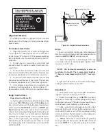
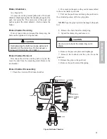
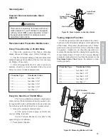
Height Control Valve
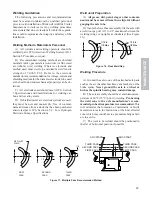
Operation (See Figure 20)
As load is applied, the horizontal actuating lever arm
moves from NEUTRAL position to UP (intake) posi-
tion. As load is removed, the horizontal actuating lever
arm moves from NEUTRAL position to DOWN (ex-
haust) position. The valve opens and air is allowed to
exhaust from air springs bringing the horizontal actu-
ating lever arm back to a neutral position. Optimum
performance is achieved when valve is adjusted accu-
rately to the suspension by increasing or decreasing
horizontal lever arm length to a point where valve and
lever arm approach 45º maximum, up or down from
neutral position.
Figure 20. Height Control Valve Asm
Set Up
1. Insert vertical link rod through offset dampener
link. Do not tighten clamp until final adjustment (dis-
cussed in ADJUSTMENT section) is made.
2. Insert horizontal lever arm through 5/16" cap
screw side of insert to desired length. Tighten 5/16"
cap screw to 10 Ft. Lbs.
NOTE: The horizontal actuating lever arm can
be adjusted in length. The recommended length is
7", however a maximum length of 11-1/2" is accept-
able.
A right or left-hand valve can be achieved by simply
rotating the horizontal lever arm 180º.
Adjustment
1. With vehicle on level ground, build and maintain
supply air pressure in excess of 65 P.S.I.
2. Rotate horizontal lever arm DOWN to exhaust
air spring or rotate UP to inflate springs until proper
ride height is achieved. Place lever arm at neutral posi-
tion and insert wood centering pins into valve.
3. Slide vertical link rod through hole in the offset
dampener link. Install vertical link rod grommet to pin
on mounting bracket at axle. Place mounting bracket
on axle and attach. Tighten clamp on offset dampener
link and remove wood centering pins.
4. TEST: Disconnect vertical link rod grommet
from mounting bracket at axle pin. Rotate horizontal
lever arm DOWN to exhaust air springs about half-
way.
45…
90…
(Optimal)
45…
Max
Up
Height Adjustable
at Hose Clamp
Actuating Lever Arm
Max
Down
YOUR SUSPENSION WILL HAVE THIS
LABEL ABOVE THE ECCENTRIC BOLT
NOTICE!
ECCENTRIC BOLT ARROW
MUST BE AT 12 O’CLOCK
POSITION PRIOR TO
ALIGNMENT. AFTER
ALIGNMENT INSTALL
ANTI-TURN WASHER OVER
HEAD OF BOLT AND TORQUE
TO 1,000 FT. LBS.


