


32
MAINTENANCE
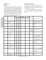
Cleaning and Inspection of Parts
Clean the metal parts in a solvent. Inspect all the
parts for damage, wear or deterioration and replace de-
fective parts.
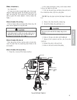
Brake Chamber Assembly
1. Stand the push rod assembly on a flat surface.
2. Put the return spring in position.
3. Place the non-pressure plate over the push rod.
4. Push the non-pressure plate down against the flat
surface. Hold it in place with vise grip pliers clamped
to the push rod.
NOTE: Tape the grips to prevent damage to the push
rod.
5. Place the clamp ring over the non-pressure plate
clamping surface.
6. Position the diaphragm in the pressure plate. As-
semble it with the non-pressure plate by working the
clamp ring over the pressure plate. Align all the marks
made during disassembly.
7. Draw the clamp lugs together. Start the clamp
bolts and nuts. Tighten the nuts to a maximum torque
of 130 inch lbs. (14.7 N.M..)
CAUTION
Overtightening the bolts can cause permanent
distortion of the clamp ring.
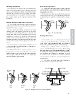
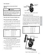
Installation
Place the brake chamber in the mounting bracket and
tighten the nuts on the studs. The drain hole must be
placed in the down position. Install the yoke and the
locknut on the push rod. Connect the push rod to the
slack adjuster with the yoke pin. Adjust the brakes.
Check the angle formed by the slack adjuster and the
push rod with the brakes applied. This angle must not
be less than 90
0
with the brakes adjusted. Turn the yoke
to obtain this angle. The angle must be the same for all
slack adjusters to obtain equal braking force at all
wheels.
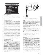
Air Brakes
General
Etnyre trailers are equipped with cam actuated
brakes. Braking force is supplied by air pressure in the
brake chamber, which pushes a push rod against the
end of the slack adjuster. The slack adjuster rotates the
camshaft, which forces the brake shoes against the brake
drum.
Operating Checks
Periodically check the brake drums for heating.
A cool brake drum may indicate an inoperative brake.
WARNING
Proceed cautiously. Malfunctioning or
misaligned brakes can cause the drum to
become extremely hot. Do not operate the
vehicle until the problem causing the
overheating is corrected.
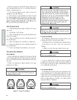
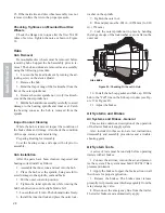
Brake Assembly
Examine the brake linings visually to locate the lin-
ing showing the greatest amount of wear.
CAUTION
Do Not
allow the linings to wear thin enough so
the lining bolts or rivets contact the drum.
Grease the anchor pins, camshaft bracket bearing and
the spider busing at four (4) grease fittings. Do Not use
an excessive amount of grease on the anchor pins and
spider bushing. Avoid getting grease on the brake lin-
ing surfaces. (See Figure 27)
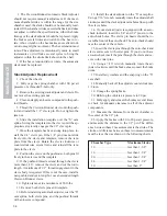
Figure 27. Brake Components
1. Shoe/Lining
7. Roller Cam
2. Spider Assembly
8. Retract Spring
3. Anchor Pin
9. Retention Spring
4. Bushing
10. Brake Assembly- LH & RH
5. Pin
6. Retainer
1
1
2
3
4
5
6
7
8
9
10
10
10
11


