background image


         Use and maintenance manual 

         Automatic die cutter  


         Model: DC-200 

__________________________________________________________________________________________________________________________________________________________________________ 


P a g   2 4


-


Pneumatic drawing 


Содержание DC-200

Страница 1: ...and maintenance manual Type Automatic die cutter 2000mm Model DC 200 IMPORTANT Read this user manual and follow the instructions and warnings before operating this device Any modification or transformation performed on this machine may cause loss of the manufacturer s guarantee and liability This manual must always remain near to the machine and visible to all the operating and maintenance staff f...

Страница 2: ...escription 4 Technical characteristics 4 Installation and connection 4 Using instructions 6 Safety systems and messages 7 Programming 8 Belt cutting measures for the different dies 9 DIE CUTTING A A Direct finger 9 DIE CUTTING A A Finger over finger 13 DIE CUTTING A B for High profile belts at 90º 16 DIE CUTTING A B Diagonal 70º 18 Changing die head 20 Care and maintenance 21 Troubleshooting 22 Pn...

Страница 3: ... Inspired by the directives of the Official Journal of the European Communities 2006 42 CE Machinery Directive 2014 35 UE Low Voltage Directive 2014 30 UE Electromagnetic Compatibility Directive Complies with the design and construction specifications of the European Standards on General Machine Safety EN 349 EN 614 1 EN 614 2 EN 1005 1 EN 1005 2 EN 1005 3 EN 1005 4 EN 14118 EN 12100 EN 13850 EN 1...

Страница 4: ...different cutting geometries with possibility of programming diverse forward steps Support bench with material positioning guides This die cutter is especially designed to cut thermoplastic materials with interior tissue Technical characteristics Dimensions 2677x930x1160 l x w x h Weight 315 Kg Max Thickness 8 mm Voltage 1x230V Power 0 40kW Max pressure 7 bar Installation and connection Place the ...

Страница 5: ...______________ P a g 5 Level and balance the machine by means of the regulation bolts on the rubber feet Provide compressed air through a tube with minimum interior diameter of 8 mm connected to the intake NOTE We must bear in mind that air consumption by this die cutter is 220 litres minute We shall connect the power cable to the control board at 230v monophasic ...

Страница 6: ...r and power be run hanging from above to prevent personnel tripping or falling Using instructions WARNING THIS DEVICE INVOLVES THE HAZARD OF HANDS AND ARMS BEING TRAPPED BY THE MOVEMENT OF THE CUTTING HEAD GREAT CARE MUST ALSO BE TAKEN BETWEEN THE CUTTING HEAD AND THE SUPPORT PLATE AS THERE IS A DANGER OF CUTTING LIMBS Once the machine is connected to the mains and provided with air we shall proce...

Страница 7: ...OP This system allows an emergency stop to be performed at any time using the two push buttons located at both ends of the bench MESSAGE EMERGENCY BUTTON PRESSED To deactivate it we must unlock the push button and then press RESET to return the head to the starting point CLAMP OPEN This device does not allow engagement of the cutting head if the bar holding the belt is not lowered MESSAGE CLAMP OP...

Страница 8: ...st know the functions of the push buttons on the board to program the die cutter 1 RESET This must be pressed after an emergency stop or position the head at the starting point after STOP 2 A A Selection of the A A program This program is used in the majority of cases to always operate on the left guide rail and cut the belts performing the first end with the coverage on top and the second end wit...

Страница 9: ...shall press this button to program the cutting process by means of the head assembled with the numerical keyboard introduce the value in milometers between 3mm to 50mm to accept the numerical value press ENTER 8 TIME We shall press this button to program the cut time using the numerical keyboard the numbers accepted are between 3 to 10 to accept the number press ENTER 9 ESC We shall use this key t...

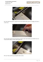
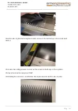
Страница 10: ..._________________________________ P a g 1 0 We then mark the measure to input the relevant material with a pencil according to the die we want to use We then place the belt under the tread bar until the mark made matches up with 0 Ref and we make sure it is fully in contact with the guide rail We lower the tread bar by pressing the down button ...

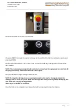
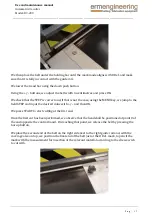
Страница 11: ...t If it is not we use the STEP key and input the desired value after ENTER NOTE The values programmed shall not be lost even when the equipment is switched off the program always memorises the last values input We press START to begin cutting at the first end NOTE During the cutting process no programmed value may be changed except the cutting time To do so we press STOP and change that value pres...

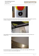
Страница 12: ...d end of the belt on the left side by the guide rail but the opposite way that is with the coverage down and position the end of the belt just on the O Ref mark Then mark the measurement to feed in the material with a pencil according to the die one wishes to use We then feed in the belt under the holding bar until the mark made aligns with 0 Ref and we make sure it is fully in contact with the gu...

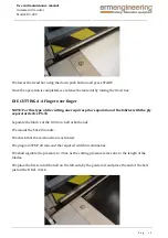
Страница 13: ... A A Finger over finger NOTE For this type of die cutting one requires prior separation of the fabrics with the ply separator device PS 15 Separate the fabrics of the 130 mm belt at both ends We mount the 50x20 mm die We check that the A A function is activated We program STEP 20 mm and the required width in centimetres We shall regulate the pressure to 3 bar as the cutting pressure is less due to...

Страница 14: ...hen pencil mark the two measures to insert the material for the stops STEP 1 and STEP 2 We then insert the material up to the first mark STEP 1 We lower the tread bar using the push button to lower it and press START Once the first cutting operation has ended we shall withdraw the surplus material We shall place the anti cut plate between the two cloths up to the end of the separator cut ...

Страница 15: ..._____________________________ P a g 1 5 Once the anti cut plate has been placed inside we insert the material up to the second mark STEP 2 We reduce the cutting pressure to 2 bar as the second cut shall only cut the top fabric We lower the tread bar and press START On finishing the second cut we withdraw the surplus material and the anti cut plate ...

Страница 16: ... High profile belts at 90º We select function A B if it is not activated We mount the die chosen 80x10 or 120x15 We program the relevant gauge for the die mounted and program the width in centimetres We adjust the cutting pressure according to the hardness of the belt and the blade length First we place the first end of the belt on the left side by the guide rail and then position the end of the b...

Страница 17: ...s correct and if that is not the case using the MENU key we jump to the field STEP and input the desired value with and then OK We press START to start cutting at the first end Once the first cut has been performed we observe that the head shall be positioned at point 0 of the end opposite the control board On reaching that point we release the belt by pressing the bar up button We place the secon...

Страница 18: ...rail We lower the tread bar using the down push button and press START Once the operation has ended we release the material by raising the pressing bar DIE CUTTING A B Diagonal 70º We select the A B function if it is not activated We mount die 80x10 70º We program the STEP to 10mm We adjust the cutting pressure to 4 6bar We program the width in centimetres 10 wider than the belt width Example if t...

Страница 19: ...___________________________________ P a g 1 9 We place the belt that has already been cut in diagonal at 70º along with the supplementary guide to mark from 0 Ref with the advance measurement of 80x10 70º We then insert the belt until it aligns with the mark made at point 0 Ref We lower the tread bar using the down push button and press START ...

Страница 20: ...he raise bar button We place the second end of the belt on the right side by the right diagonal guide and with the coverage also on top and position the far end of the belt just at the O Ref mark to pencil the measurement mark to insert the material that will be 80x10 70º We then insert the material till the mark aligns with 0 Ref and lower the tread bar and press START Changing die head WARNING W...

Страница 21: ...in We close the rear door and program the correct gauge on MENU STEP OK NOTE We must adjust the cutting pressure for each type of die or material Otherwise excess pressure may cause breakage of the blades or deterioration of the cutting nylon Care and maintenance Keep the screw and linear guides dust free and well lubricated with low density low silicone content lubricant oil Replace the blades or...

Страница 22: ...sin if there is condensation in the line Troubleshooting The board does not turn on Check whether the switch LED turns red to determine a possible problem in the electric power line to the machine The head does not move at all Check that the cylinder is upward and that the grid cylinder cutting detector is on The head moves but does not cut Check that the electro valve is working and that the conn...

Страница 23: ...r Model DC 200 ____________________________________________________________________________________________________________________ P a g 2 3 NOTE In the event of any problem pay special attention to the messages on the screen to find what is wrong ...

Страница 24: ...tomatic die cutter Model DC 200 __________________________________________________________________________________________________________________________________________________________________________ P a g 2 4 Pneumatic drawing ...

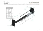
Страница 25: ... n 771 01 70220 671 01 N um ber P art nam e U nits K n771 01 cuchilla 0 7x1 22xdoblebisel norm al par 2 70200 D istancial troquel 1 20D C par 1 70220 P asador troquel par 2 671 01 T R O Q U E L 1 20x1 5 par 1 PUNCHING PLATE 120X15 PUNCHING PLATE 80X10 70200 K n771 02 70220 671 02 N um ber P art nam e U nits K n771 02 cuchilla 0 7x82xdoblebisel norm al par 2 70200 D istancial troquel 1 20D C par 1 ...

Страница 26: ...º PUNCHING PLATE 50X20 70200 K n 771 03 K n 771 04 671 03 N u m ber P art nam e U nits K n771 03 cuchilla 0 7x79 5 70 par 1 K n771 04 cuchilla 0 7x82 5 70 par 1 70200 D istancial troquel 1 20D C par 1 70220 P asador troquel par 2 671 03 T R O Q U E L 80X 1 0 70 par 1 70220 70200 K n771 05 671 04 N um ber P art nam e U nits K n771 05 cuchilla 0 7x52 5 par 2 70200 D istancial troquel 1 20D C par 1 7...

Страница 27: ... nits 701 00 C D Q 2B 1 40T F 40D C Z asm 1 701 01 C abeza C D 1 500 asm 1 701 02 P atinH iw in20 par 2 701 03 K Q 2L 1 2 03S par 4 701 04 S Y 91 20 5D Z 03 asm 1 701 05 S crew _D IN _91 2_M 1 4x50_v1 0 00 par 4 701 06 K Q 2S 1 0 03S par 1 701 07 A N A 1 02 par 2 701 08 T apa traseracabezal par 1 701 09 S crew _D IN _91 2_M 6x25_v1 0 00 par 8 701 1 0 P alm _gripD IN _6335_L _20x 1 5_v1 0 00 par 1 ...

Страница 28: ..._____________________________________________________________________________________________ P a g 2 8 70201 70203 70205 70204 70206 N um ber P art nam e U nits 70201 B asedistancial par 1 70202 E nlacetroquel par 1 70203 G uia cabezal par 1 70204 S oporteguia cabeza par 1 70205 S elfoil 1 5x20x25 par 2 70206 T ornillotroquel par 2 70202 ...

Страница 29: ...manual Automatic die cutter Model DC 200 __________________________________________________________________________________________________________________________________________________________________________ P a g 2 9 ...

Страница 30: ...manual Automatic die cutter Model DC 200 __________________________________________________________________________________________________________________________________________________________________________ P a g 3 0 ...

Страница 31: ...tomatic die cutter Model DC 200 __________________________________________________________________________________________________________________________________________________________________________ P a g 3 1 Electrical drawing ...

Страница 32: ...manual Automatic die cutter Model DC 200 __________________________________________________________________________________________________________________________________________________________________________ P a g 3 2 ...

Страница 33: ...manual Automatic die cutter Model DC 200 __________________________________________________________________________________________________________________________________________________________________________ P a g 3 3 ...

Страница 34: ...manual Automatic die cutter Model DC 200 __________________________________________________________________________________________________________________________________________________________________________ P a g 3 4 ...

Страница 35: ...manual Automatic die cutter Model DC 200 __________________________________________________________________________________________________________________________________________________________________________ P a g 3 5 ...

Страница 36: ...manual Automatic die cutter Model DC 200 __________________________________________________________________________________________________________________________________________________________________________ P a g 3 6 ...

Страница 37: ...manual Automatic die cutter Model DC 200 __________________________________________________________________________________________________________________________________________________________________________ P a g 3 7 ...

Страница 38: ...manual Automatic die cutter Model DC 200 __________________________________________________________________________________________________________________________________________________________________________ P a g 3 8 ...

Отзывы: