Multi Service Edge Device HL950
Administrator’s Guide
Page 29 (159)
EN/LZT 108 5995 R3
June
2003
4.2.3.2
E1 Unstructured CES with Adaptive Clocking
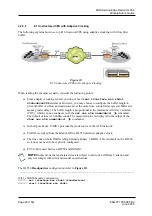
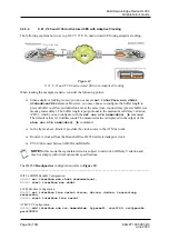
The following explains how to set up E1 Structured CES using adaptive clocking with 10ms Jitter
buffer.
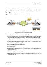
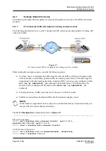
Figure 10
E1 Unstructured CES with Adaptive Clocking
When reading the example scenario, consider the following points:
!
Since adaptive clocking is used, you do not need a
set interface wan shdsl
ntrmode=ref8k
statement. However, you may choose to configure the buffer length to
prevent buffer overflow and underrun and, at the same time, control delay (greater buffer size
means greater delay). The buffer length is proportional to the maximum cell delay variation
(CDV), which you can configure with the
set ces atm name=abcd, jb
command.
The default values is 10 milliseconds. The measured value is displayed in the output of the
show ces atm name=abcd, jb
command.
!
In the figure above, PABX1 provides the clock source to the ATM network.
!
PABX2 is clocked from the Branch Office HL950 extracted adaptive clock.
!
The line code on both PABXs is High Density Binary 3, HDB3. This is default on the HL950
so it does not need to be explicitly configured.
!
PVC 0/40 is used between HL950 and DSLAM.
NOTE!
In this mode the regenerated clock is subject to network Cell Delay Variation and
may not comply with jitter and wander specifications.
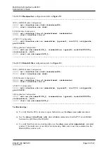
The HL950
Headquarters
configuration (refer to
Figure 10
):
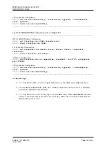
__________________________________________________________________________________
WIF 2x SHDSL Module Configuration:
HL950> set interface wan shdsl:ntrmode=local;
HL950> start interface wan shdsl


