


Multi Service Edge Device HL950
Administrator’s Guide
Page 129 (159)
EN/LZT 108 5995 R3
June
2003
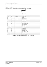
Pin
Signal
Comment
1 RX+ Receive
Positive
2 RX- Receive
Negative
3 TX+ Transmit
Positive
4
Not
connected
5
Not
connected
6 TX- Transmit
Negative
7
Not
connected
8
Not
connected
Table 3
- Pin and Signals for the Ethernet Ports
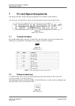
The Ethernet interfaces have MDI/MDI-X Auto Cross-over ability, which means that transmit and
receive, will be auto-detected. Transmit and receive may be swapped.
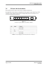
7.3 SHDSL
Interfaces
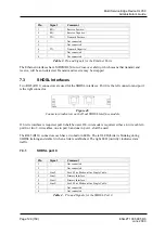
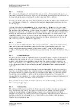
Two RJ45 (RJ11) connectors are used for the SHDSL interfaces. Port 0 is the left connector and port 1
is the right connector.
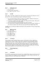
Figure 46
Connectors/indicators on the Dual SHDSL Interface module
If 2-wire interface is required, port 0 shall be used. If 4-wire mode is required, either a 4-wire cable in
port 0 or two 2-wire cables, one in port 0 and one in port 1, shall be used.
The RJ45 (RJ11) connectors each have two built-in LEDs. The left LED (
L
ink) is blinking during
SHDSL training and stable lit when a link is established. The right LED (
A
ctivity) indicates data
traffic.
7.3.1
SHDSL port 0
Pin
Signal
Comment
1
Not
connected
2
Not
connected
3
Line2-
For 4-Wire Mode on One Single Cable
4 Line1- Primary
Interface
5 Line1+ Primary
Interface
6
Line2+
For 4-Wire Mode on One Single Cable
7
Not
connected
8
Not
connected
Table 4
– Pin and Signals for the SHDSL Port 0


