


S1F76610 Series
2–12
EPSON
S1F70000 Series
Technical Manual
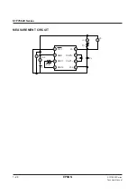
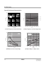
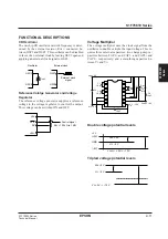
TYPICAL APPLICATIONS
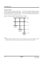
Voltage Tripler with Regulator
The following figure shows the circuit required to triple
the input voltage, regulate the result and add a tempera-
ture gradient of –0.4%/
°
C. Note that the high input im-
pedance of RV requires appropriate noise countermea-
sures.
C4
R1
R2
+
10
µ
F
V
REG
= –8 V
=
V
RV
V
I
= –5 V
R
RV
100 k
Ω
to
1 M
Ω
R
OSC
1 M
Ω
C1 +
10
µ
F
C2
5 V
+
10
µ
F
C3
+
10
µ
F
V
O
= –15 V
V
DD
= 0 V
14
13
12
11
10
9
8
1
2
3
4
5
6
7
R
RV
R
1
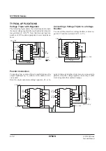
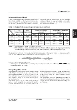
Converting a Voltage Tripler to a Voltage
Doubler
To convert this curcuit to a voltage doubler, remove ca-
pacitor C2 and short circuit CAP2– to V
O
.
V
I
= –5 V
R
OSC
1 M
Ω
C1 +
10
µ
F
C2
5 V
+
10
µ
F
C3
+
10
µ
F
V
O
= –15 V
V
DD
= 0 V
14
13
12
11
10
9
8
1
2
3
4
5
6
7
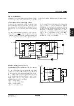
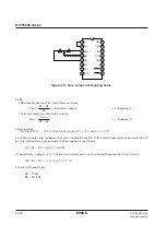
Parallel Connection
Connecting two or more chips in parallel reduces the
output impedance by 1/n, where n is the number of de-
vices used.
Only the single output smoothing capacitor, C3, is re-
V
DD
= 0 V
V
I
= –5 V
V
O
= –15 V
V
REG
= –10 V
5 V
C1
10
µ
F
R
OSC
1 M
Ω
R
OSC
1 M
Ω
+
C2
10
µ
F
+
C1
10
µ
F
+
C2
10
µ
F
+
C4
10
µ
F
R
RV
100 k
Ω
to
1 M
Ω
+
C3
10
µ
F
+
1
2
3
4
5
6
7
14
13
12
11
10
9
8
1
2
3
4
5
6
7
14
13
12
11
10
9
8
quired when any number of devices are connected in
parallel. Also, the voltage regulator in one chip is suffi-
cient to regulate the combined output.
Содержание S1F76610C0B0
Страница 4: ...S1F70000 Series Technical Manual ...
Страница 17: ...1 DC DC Converter ...
Страница 43: ...2 DC DC Converter Voltage Regulator ...
Страница 107: ...3 Voltage Regulator ...
Страница 145: ...4 DC DC Switching Regulators ...
Страница 200: ...5 Voltage Detector ...
Страница 223: ...6 Appendix ...


