


S1F76640 Series
S1F70000 Series
EPSON
2–61
Technical Manual
S1F76640
Series
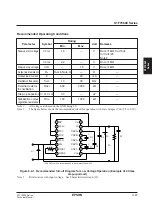
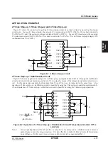
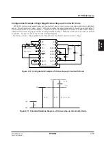
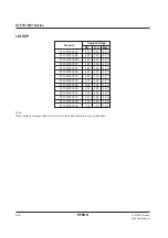
Example of Temperature Gradient Change by External Temperature Sensor (Ther-
mistor)
S1F76640 has a temperature gradient selection circuit inside the stabilization circuit, and three kinds of tempera-
ture gradients, –0.20%/˚C, –0.40%/˚C and –0.60%/˚C, can be selected as the V
REG
output. When other temperature
gradients are necessary, a thermistor is connected in series to the resistor R
RV
for output voltage regulation as shown
in Figure 8.8, and temperature gradients can be changed to any values.
Figure 8.8 Example of Temperature Gradient Change
(Pins other than the above Pins 1, 2 and 6 are connected as per Figure 5.2. For Pins 3 and 4, smaller temperature
gradients than those to be changed are selected from Table 4.1 and are set.)
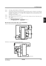
Note 1 :
Relations among the thermistor, RT and V
REG
are expressed as follows:
V
REG
=
R
RV
+ R
T
· V
RV
R
1
When a thermistor is used for RT, it can make the temperature gradient of V
REG
larger..
Note 2 :
The thermistor temperature characteristics are non-linear but can be corrected to linear ones when the
resistor RP is connected to the thermistor in parallel.
16
15
14
13
12
11
10
9
1
2
3
4
5
6
7
8
RV
V
REG
V
SS
R
P
R
1
R
T
V
REG
R
RV
Содержание S1F76610C0B0
Страница 4: ...S1F70000 Series Technical Manual ...
Страница 17: ...1 DC DC Converter ...
Страница 43: ...2 DC DC Converter Voltage Regulator ...
Страница 107: ...3 Voltage Regulator ...
Страница 145: ...4 DC DC Switching Regulators ...
Страница 200: ...5 Voltage Detector ...
Страница 223: ...6 Appendix ...


