


S1F76640 Series
S1F70000 Series
EPSON
2–47
Technical Manual
S1F76640
Series
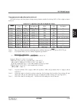
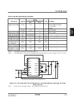
Recommended Operating Conditions
Note 1 :
All voltages are based on the GND being 0V.
Note 2 :
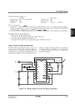
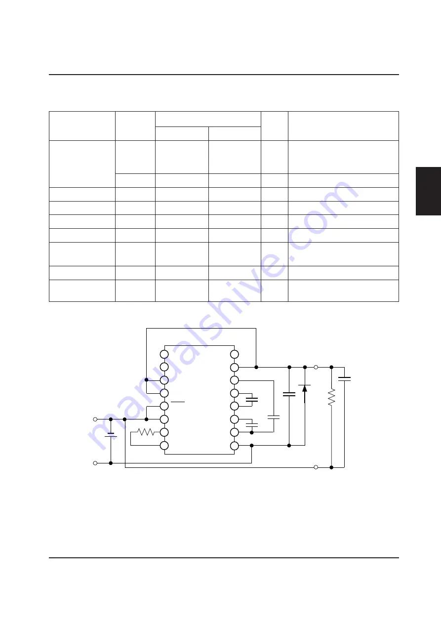
The figure below shows the recommended circuit for operation with low voltages (V
DD
=1.8 to 2.2V):
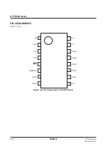
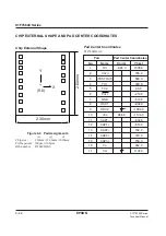
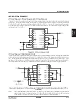
Figure 6-2-1 Recommended Circuit Diagram for Low Voltage Operation (Example of 4 times
step-up circuit)
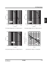
Note 3 :
R
L
min varies with input voltage. See Characteristics Graph (15).
Parameter
Symbol
Rating
Unit
Remarks
Min.
Max.
Step-up start voltage
V
STA1
1.8
—
V
R
OSC
=1M
Ω
, C
4
≥
10
µ
F
C
L
/C
4
≤
1/20
Note 2
V
STA2
2.2
—
V
R
OSC
=1M
Ω
Step-up stop voltage
V
STP
—
1.8
V
R
OSC
=1M
Ω
Output load resistance
R
L
R
L
min
Note 3)
—
Ω
—
Output load current
I
O
—
20
mA
—
Oscillation frequency
f
OSC
10
30
kHz
—
External resistor
R
OSC
680
2000
k
Ω
—
for oscillation
Step-up capacitor C
1
,C
2
,C
3
,C
4
3.3
—
µ
F
—
Stabilization output
R
RV
100
1000
k
Ω
—
regulation resistance
1
2
3
4
5
6
7
8
RV
V
REG
TC1
TC2
P
OFF
V
SS
OSC1
OSC2
V
RI
V
O
CAP3+
CAP2+
CAP2–
CAP1+
CAP1–
V
DD
16
15
14
13
12
11
10
9
V
I
C
2
C
4
C
1
C
3
+
+
+
–
D
1
R
L
C
L
(D1(VF(1F=1mA) is recommended to be not more than 0.6V.)
–
–
Содержание S1F76610C0B0
Страница 4: ...S1F70000 Series Technical Manual ...
Страница 17: ...1 DC DC Converter ...
Страница 43: ...2 DC DC Converter Voltage Regulator ...
Страница 107: ...3 Voltage Regulator ...
Страница 145: ...4 DC DC Switching Regulators ...
Страница 200: ...5 Voltage Detector ...
Страница 223: ...6 Appendix ...


