


S1F76540 Series
S1F70000 Series
EPSON
2–31
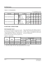
Technical Manual
S1F76540
Series
◊
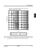
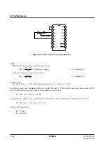
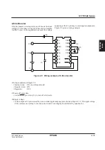
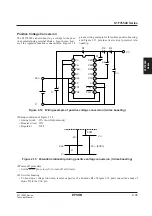
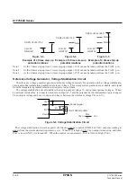
Setup conditions of Figure 2.9
• Internal clock : ON (Low Output mode)
• Booster circuit : ON
• Regulator
: OFF
◊
Power-off procedure
• Set the P
OFF2
pin to low (V
I
) to turn off all circuits.
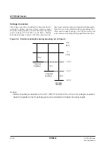
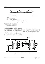
◊
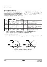
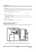
Ripple voltage
• As the output at V
O
pin is unstable, it can contain ripple components as shown in Figure 2.10. The ripple voltage
(V
RP
) increases according to the load current, and it can roughly be calculated by equation (4).
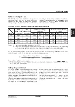
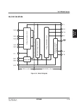
Figure 2.9 Wiring example of 4-time booster
V
O
V
RI
V
REG
RV
V
DD
FC
TC1
TC2
C2P
C2N
C3N
C1N
C1P
V
I
P
OFF1
P
OFF2
C2
C1
C3
1
2
3
4
5
6
7
8
C
I
V
I
V
DD
V
O
C
O
+
+
+
16
15
14
13
12
11
10
9
+
+
4-time Booster
Only the booster circuit operates, and it boosts the input
voltage (V
I
) four times in negative direction and outputs
it at the V
O
pin. As the regulator is not used, the voltage
appearing at the V
O
pin may contain ripple components.
Figure 2.9 gives a wiring example.
Содержание S1F76610C0B0
Страница 4: ...S1F70000 Series Technical Manual ...
Страница 17: ...1 DC DC Converter ...
Страница 43: ...2 DC DC Converter Voltage Regulator ...
Страница 107: ...3 Voltage Regulator ...
Страница 145: ...4 DC DC Switching Regulators ...
Страница 200: ...5 Voltage Detector ...
Страница 223: ...6 Appendix ...


