ENVIRO-TEC
9
FORM ET115.24-NOM4 (819)
LIST OF TABLES
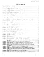
FIGURE 45
- Assembly Instructions Return Panel with Latches, Quick Opening or Tamper Proof,
Model VHC/VHM/VHS High Rise FCU ............................................................................................. 65
FIGURE 46
- Preparation Instructions for Model VHC/VHM Vertical High Rise FCU "Ship Loose"
Riser Assemblies ..............................................................................................................................66
FIGURE 47
- Full Louvered Aluminum Return Air/Wall Panel Model VH Vertical High Rise Fan Coil Unit ............ 67
FIGURE 48
- Model VH Vertical High Rise Fan Coil Unit Standard Surface Mount Wall Panel ............................. 68
FIGURE 49
- Recessed Wall Panel Model VH Vertical High Rise Fan Coil Unit .................................................... 69
FIGURE 50
- Model VH Vertical High Rise Fan Coil Unit Standard Return Wall Panel with ADA Thermostat ....... 70
FIGURE 51
- Suggested Riser Floor Openings VHC & VHM ................................................................................. 73
FIGURE 52
- Riser Terminology, Model VHC, VHM, VHA Units ............................................................................. 74
FIGURE 53
- Standard Installation .........................................................................................................................76
FIGURE 54
- Alternate Installation .........................................................................................................................76
FIGURE 55
- Mounting Details ...............................................................................................................................77
LIST OF FIGURES (CONT'D)
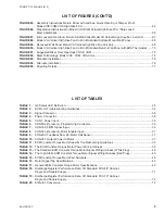
TABLE 1
- G3 Status LED Definition ....................................................................................................................25
TABLE 2
- EC Motor Troubleshooting Guidelines ................................................................................................ 32
TABLE 3
- Signal Connector ................................................................................................................................36
TABLE 4
- Power Connector ................................................................................................................................36
TABLE 5
- CON1, Power Input ............................................................................................................................36
TABLE 6
- CON502 (if present), Programming Connector .................................................................................. 36
TABLE 7
- CON302, PWM Signal Input ............................................................................................................... 36
TABLE 8
- CON503 (if present), Motor Enable Input ........................................................................................... 37
TABLE 9
- CON202, Feedback from EC Motor Hall Sensor ................................................................................ 37
TABLE 10
- CON201, Output Power to Motor ....................................................................................................... 37
TABLE 11
- ECM Constant Torque Motor Specific Troubleshooting Guidelines
.................................................... 38
TABLE 12
- The ECM Constant Torque Motor Power Wiring Harness
.................................................................. 39
TABLE 13
- The Standard ECM Constant Torque Motor Signal Wiring Harness (White Plug)
.............................. 40
TABLE 14
- The High Static ECM Constant Torque Motor Signal Wiring Harness (Red Plug)
.............................. 40
TABLE 15
- ECM Constant Torque Motor Part Numbers
....................................................................................... 40
TABLE 16
- Motor Signal Tap Specifications.......................................................................................................... 40
TABLE 17
- General ECM Constant Torque Motor Specifications
......................................................................... 40
TABLE 18
- Discharge Register Performance Data, VH Standard FCU 88" Cabinet,
Single and Double Supply ..................................................................................................................71
TABLE 19
- Discharge Register Performance Data, VH Standard FCU 79" Cabinet,
Single and Double Supply ..................................................................................................................72
TABLE 20
- SI Metric Conversion ..........................................................................................................................79
Содержание VHA
Страница 10: ...ENVIRO TEC 10 FORM ET115 24 NOM4 819 THIS PAGE INTENTIONALLY LEFT BLANK ...
Страница 22: ...ENVIRO TEC 22 FORM ET115 24 NOM4 819 SECTION 1 RECEIPT INSTALLATION THIS PAGE INTENTIONALLY LEFT BLANK ...
Страница 41: ...ENVIRO TEC 41 SECTION 2 START UP FORM ET115 24 NOM4 819 THIS PAGE INTENTIONALLY LEFT BLANK ...
Страница 54: ...ENVIRO TEC 54 FORM ET115 24 NOM4 819 SECTION 6 Dimensional Data 74 80083 ...
Страница 78: ...ENVIRO TEC 78 FORM ET115 24 NOM4 819 SECTION 6 Dimensional Data NOTES ...


