ENVIRO-TEC
8
FORM ET115.24-NOM4 (819)
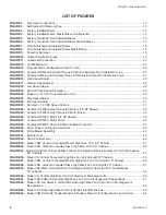
LIST OF FIGURES
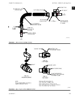
FIGURE 1
- Flex Hose Connections .....................................................................................................................13
FIGURE 2
- Ball Valve With Memory Stop............................................................................................................ 13
FIGURE 3
- Factory Installed Risers ....................................................................................................................14
FIGURE 4
- Factory Installed Risers, Master/Slave Configuration
....................................................................... 15
FIGURE 5
- Factory Furnished, Field Installed Risers ......................................................................................... 15
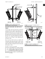
FIGURE 6
- Factory Furnished, Field Installed Risers, Master/Slave .................................................................. 15
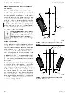
FIGURE 7
- Field Furnished and Installed Risers ................................................................................................ 16
FIGURE 8
- Field Furnished and Installed Risers Master/Slave .......................................................................... 16
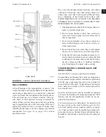
FIGURE 9
- Knockout Removal ............................................................................................................................18
FIGURE 10
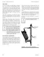
- Critical Penetration Areas ................................................................................................................. 19
FIGURE 11
- Outside Air Connection .....................................................................................................................20
FIGURE 12
- G3 PWM Board .................................................................................................................................25
FIGURE 13
- Program Mode (Configuration Switch 1 ON)
.................................................................................... 26
FIGURE 14
- Constant RPM and Constant Torque EC Motors Example Fan Calibration Curve
........................... 27
FIGURE 15
- Constant Airflow and Constant Torque EC Motors Example Fan Calibration Curve
........................ 27
FIGURE 16
- High Speed Adjust ............................................................................................................................28
FIGURE 17
- Medium Speed Adjust .......................................................................................................................28
FIGURE 18
- Low Speed Adjust .............................................................................................................................29
FIGURE 19
- Normal Three Speed Operation ........................................................................................................ 29
FIGURE 20
- Mode to 2–10 VDC Proportional Control .......................................................................................... 30
FIGURE 21
- Max Speed Adjust .............................................................................................................................30
FIGURE 22
- Min Speed Adjust ..............................................................................................................................31
FIGURE 23
- Normal 2 – 10 VDC Speed Control ................................................................................................... 31
FIGURE 24
- Constant CFM/Constant Torque EC Motors (1/3 HP Shown)
........................................................... 35
FIGURE 25
- Constant CFM/Constant Torque EC Motor Driver
............................................................................. 35
FIGURE 26
- Constant RPM EC Motor (1/4 HP Shown) ........................................................................................ 36
FIGURE 27
- Constant RPM EC Motor Driver ........................................................................................................ 36
FIGURE 28
- Constant RPM EC Driver EC Motor Enable Connector .................................................................... 37
FIGURE 29
- Motor Power and Signal Connectors ................................................................................................ 39
FIGURE 30
- Motor/Blower Assembly .................................................................................................................... 42
FIGURE 31
- Electric Heat .....................................................................................................................................43
FIGURE 32
- Drain Pan Removal ...........................................................................................................................44
FIGURE 33
- Model VHM, Vertical Concealed Master High Rise, FCU, 88" Cabinet ............................................ 51
FIGURE 34
- Model VHS, Vertical Concealed Slave High Rise, FCU, 88" Cabinet ............................................... 52
FIGURE 35
- Model VHA/VHB, Vertical Hi-Rise Tandem Fire Rated and Non-Fire Rated, FCU Combinations,
88" Cabinets .....................................................................................................................................53
FIGURE 36
- Model VH, Vertical Concealed High Rise Fan Coil Unit with 79" Cabinet ......................................... 55
FIGURE 37
- Model VHM, Vertical Concealed Master High Rise Fan Coil Unit with 79" Cabinet .......................... 56
FIGURE 38
- Model VHS, Vertical Concealed Slave High Rise Fan Coil Unit with 79" Cabinet ............................ 57
FIGURE 39
- Model VHA/VHB, Vertical Hi-Rise Fire Rated and Non-Fire Rated FCU Combinations,
79" cabinets ......................................................................................................................................58
FIGURE 40
- Model VH, Vertical High Rise Coil Unit, Aluminum Discharge Grille ................................................. 60
FIGURE 41
- Model VHC/VHM/VHA Vertical High Rise Fan Coil Unit Arrangement Designations ........................ 61
FIGURE 42
- Model VHC w/o Risers & VHS/VHB Vertical High Rise Fan Coil Units, Unit Arrangement
Designations .....................................................................................................................................62
FIGURE 43
- Model VH Vertical High Rise Coil Unit Outside Inlet Dimensions ..................................................... 62
FIGURE 44
- Model VHM/VHA/VHC Tandem Master & Tandem Slave Unit Configuration Fan Coil Unit
.............. 64
Содержание VHA
Страница 10: ...ENVIRO TEC 10 FORM ET115 24 NOM4 819 THIS PAGE INTENTIONALLY LEFT BLANK ...
Страница 22: ...ENVIRO TEC 22 FORM ET115 24 NOM4 819 SECTION 1 RECEIPT INSTALLATION THIS PAGE INTENTIONALLY LEFT BLANK ...
Страница 41: ...ENVIRO TEC 41 SECTION 2 START UP FORM ET115 24 NOM4 819 THIS PAGE INTENTIONALLY LEFT BLANK ...
Страница 54: ...ENVIRO TEC 54 FORM ET115 24 NOM4 819 SECTION 6 Dimensional Data 74 80083 ...
Страница 78: ...ENVIRO TEC 78 FORM ET115 24 NOM4 819 SECTION 6 Dimensional Data NOTES ...


