ENVIRO-TEC
20
FORM ET115.24-NOM4 (819)
SECTION 1 - RECEIPT & INSTALLATION
MOTORIZED OUTSIDE AIR DAMPER
The standard motorized outside air damper is factory
wired to open the damper when the fan is operating.
Other damper operating sequences are available. See
individual order documents to verify actual damper
operation.
The motorized outside air damper is factory set to drive
from full closed to full open. The damper may be ad-
justed in the field to set the desired amount of outside
air by the following steps:
1. Loosen the set screw in the damper actuator set
collar and turn on all power and set all controls
to call for full outside air. This should drive the
damper actuator to the “full open” position.
2. Manually position the damper blade to achieve
the desired amount of outside air.
3. Tighten the set screw to lock the damper blade to
the actuator set collar.
4. Disconnect power or set controls to de-energize
the outside air, and verify that the damper drives
to the “closed” position.
5. Re-energize the outside air and verify that the
damper returns to the position set in Step 2.
ELECTRICAL CONNECTIONS SHOCK /
ELECTRICAL HAZARDS
The unit nameplate lists the unit electrical characteris-
tics such as the required supply voltage, fan and heater
amperage, unit minimum circuit ampacity, and maxi-
mum overcurrent protective device. The unit-wiring
diagram shows all unit and field wiring. Since each
project is different and each unit on a project may be
different, the installer must be familiar with the wiring
diagram and nameplate on the unit BEFORE beginning
any wiring. Provide for adequately sized fuse, circuit
breaker or disconnect means as applicable to meet lo-
cal and national electrical codes. All electrical connec-
tions should be checked for tightness prior to startup.
All components furnished for field installation, by ei-
ther the factory or the controls contractor should be
located and checked for proper function and compat-
ibility. All internal components should be checked for
shipping damage and any loose connections should be
tightened to minimize problems during startup.
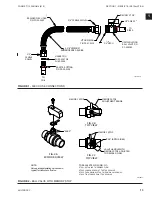
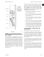
AIR DAMPER
OUTSIDE
MOTORIZED
AIR DAMPER
MANUAL OUTSIDE
FIGURE 11 -
OUTSIDE AIR CONNECTION
OUTSIDE AIR CONNECTION
The optional 6” diameter round outside air connec-
tion is provided with either a round butterfly manual
damper, or a rectangular motorized damper assembly,
for outside air control. See
Figure 11 on page 20
for
details. Installation of outside air duct connections may
require installation of a vapor barrier between the unit
and the wall, and may require freeze protection con-
trol devices. These components must be supplied and
installed by others as required. It is recommended that
all outside air be pretreated to regulate its temperature
and humidity ratio.
MANUAL OUTSIDE AIR DAMPER
The manual outside air damper may be adjusted by
loosening the wing nuts on the top and bottom, and
setting the adjustment lever to the required position for
the desired amount of outside air. The wing nuts are
then tightened to lock the damper in place.
LD13877
Содержание VHA
Страница 10: ...ENVIRO TEC 10 FORM ET115 24 NOM4 819 THIS PAGE INTENTIONALLY LEFT BLANK ...
Страница 22: ...ENVIRO TEC 22 FORM ET115 24 NOM4 819 SECTION 1 RECEIPT INSTALLATION THIS PAGE INTENTIONALLY LEFT BLANK ...
Страница 41: ...ENVIRO TEC 41 SECTION 2 START UP FORM ET115 24 NOM4 819 THIS PAGE INTENTIONALLY LEFT BLANK ...
Страница 54: ...ENVIRO TEC 54 FORM ET115 24 NOM4 819 SECTION 6 Dimensional Data 74 80083 ...
Страница 78: ...ENVIRO TEC 78 FORM ET115 24 NOM4 819 SECTION 6 Dimensional Data NOTES ...

