ENVIRO-TEC
26
FORM ET115.24-NOM4 (819)
SECTION 2 - START-UP
G3 PWM Status Descriptions
Normal
- (Run mode) - If configuration switch 1 is in
Run Mode (OFF) the LED will flash to indicate Nor-
mal status.
Timed Out
- (Program Mode) - The PWM board has a
time out function in Program Mode. If the PWM board
has timed out in Program Mode, the LED will flash.
Time Out may be cleared by pushing the Reset Button.
Error
- (Run Mode) - If configuration switch 1 is in
Run mode (OFF) and the LED is always ON, there is
a system error. Verify all connections and proper input
voltage at Line and Com, then push the Reset Button.
If this fails to return the board to Normal mode, replace
the board.
Program Mode
- If configuration switch 1 is in Pro-
gram Mode (ON) the LED will be always ON to indi-
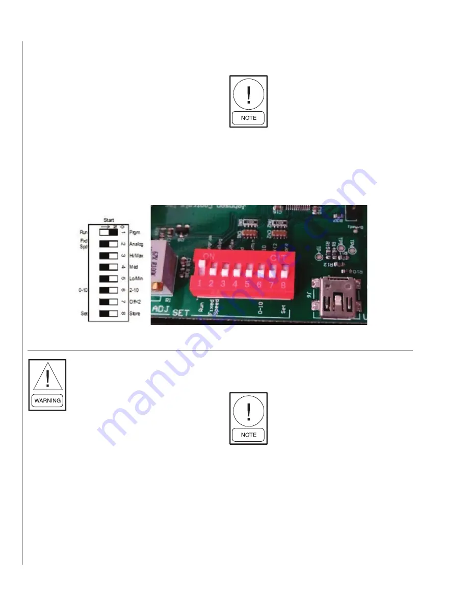
cate that the board is in Program Mode. See Figure 2.
While in Program Mode, the fan motor
will not run.
Fault
- (Any mode) - If the LED remains OFF, the
board either has no power or is faulted. Verify proper
input voltage at Line and Com, then push the Reset
Button. If this fails to return the board to expected
mode, replace the board.
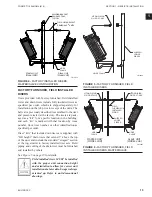
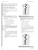
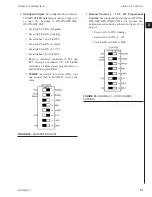
FIGURE 13 -
PROGRAM MODE (CONFIGURATION SWITCH 1 ON)
All power must be disconnected prior to
installation and servicing this equipment.
More than one source of power may be
present. Disconnect all power sources
to avoid electrocution or shock injuries.
Refer to lock out tag out procedures.
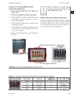
1. Make sure there are no obstructions in the dis-
charge ductwork and/or at the plenum opening.
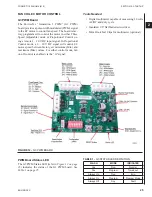
2. Locate the G3 PWM board in the control enclo-
sure. Refer to Figure 1 for location of test points
TP3 and TP1, the Configuration Switch, Speed
Adjust Potentiometer, and Reset Button.
3.
Place Configuration Switch into Program Mode.
Use an insulated screwdriver to flip configuration
switch #1 (closest to speed adjust potentiometer)
to the ON position. See
Figure 13 on page 26
.
4. Press Reset button. Connect a voltmeter to test
points TP1 (-) and TP3 (+). Refer to Figure 1. Set
voltmeter to DC volts.
The PWM board must be in Program
Mode to read voltage across TP1 and TP3.
5. Apply power to the unit. Verify that the status LED
is Always On, indicating that the PWM board is in
Program Mode. If the status LED blinks while in
Program Mode, the board has timed out. In this
case, push the reset button and verify the status
LED returns to Always On.
LD19221
LD19220
Содержание VHA
Страница 10: ...ENVIRO TEC 10 FORM ET115 24 NOM4 819 THIS PAGE INTENTIONALLY LEFT BLANK ...
Страница 22: ...ENVIRO TEC 22 FORM ET115 24 NOM4 819 SECTION 1 RECEIPT INSTALLATION THIS PAGE INTENTIONALLY LEFT BLANK ...
Страница 41: ...ENVIRO TEC 41 SECTION 2 START UP FORM ET115 24 NOM4 819 THIS PAGE INTENTIONALLY LEFT BLANK ...
Страница 54: ...ENVIRO TEC 54 FORM ET115 24 NOM4 819 SECTION 6 Dimensional Data 74 80083 ...
Страница 78: ...ENVIRO TEC 78 FORM ET115 24 NOM4 819 SECTION 6 Dimensional Data NOTES ...

